montwill M1 Series User Manual
Hide thumbs
Also See for M1 Series:
- User manual (28 pages) ,
- User manual (20 pages) ,
- User manual (20 pages)
Table of Contents
Advertisement
Quick Links
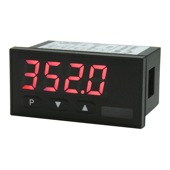
User Manual M1
Current loop 4-20 mA
Installation size 96x48 mm (BxH)
Installation size mm (BxH)
Technical features:
• red display of -1999...9999 digits
• minimal installation depth: 25 mm, 26 mm, 27 mm or 40 mm without plug-in terminal
• adjustment via factory default or directly on the sensor signal
• min/max-memory
• 10 adjustable supporting points
• display flashing at threshold exceedance / undershooting
• tara function
• programming interlock via access code
• protection class IP65 at the front
• plug-in terminal
• pc-based configuration software PM-TOOL with CD and USB-adapter for devices
without keypad for a simple adjustment of standard devices
M1_xSGB.pdf update: 27.05.2020
Installation size 48x24 mm (BxH)
Installation size 72x36 mm (BxH)
Current loop
Advertisement
Table of Contents

Related Manuals for montwill M1 Series


Summary of Contents for montwill M1 Series
- Page 1 User Manual M1 Current loop 4-20 mA Installation size 48x24 mm (BxH) Installation size 96x48 mm (BxH) Installation size mm (BxH) Installation size 72x36 mm (BxH) Technical features: • red display of -1999…9999 digits • minimal installation depth: 25 mm, 26 mm, 27 mm or 40 mm without plug-in terminal •...
- Page 2 Identification – Current loop 4-20 mA STANDARD TYPES ORDER NUMBER Housing dimension: M1-1SR4B.0001.K70xD 96x48x38 mm (incl. plug-in terminal) M1-1SR4B.0001.K70xD Housing dimension: M1-3SR4B.0001.K70xD 96x24x63 mm (incl. plug-in terminal) M1-3SR4B.0001.K70xD Housing dimension: M1-6SR4B.0001.K70xD 72x36x38 mm (incl. plug-in terminal) M1-6SR4B.0001.K70xD Housing dimension: M1-7SR4A.0001.K70xD 48x24x54 mm (incl.
-
Page 3: Table Of Contents
Content 1. Brief description 2. Assembly 3. Electrical connection and connection examples 4. Function description and operation 4.1. Programming software PM-TOOL 5. Setting up the device 5.1. Switching on 5.2. Standard parameterisation (flat operation level) Value assignment for control of the signal input 5.3. -
Page 4: Brief Description
1. Brief description 1. Brief description The panel instrument M1-XS is a 4-digit device fed via current loop 4-20 mA and a visual limit value monitoring via the display. The configuration happens via three front keys or via the optional PC-software PM-TOOL. An integrated programming interlock prevents unrequested changes of the parameter and can be unlocked again via an individual code. -
Page 5: Assembly
2. Assembly 2. Assembly Please read the Safety advice on page 19 before installation and keep this user manual for future reference. The example given below shows a device in housing size 96x48mm. Gap for physical unit 1. After removing the fixing elements, insert the device. 2. -
Page 6: Electrical Connection And Connection Examples
3. Electrical connection 3. Electrical connection Type M1-1SR4B.0001.K70xD (Housing 96x48 mm) Type M1-3SR4B.0001.K70xD (Housing 96x24 mm) Type M1-6SR4B.0001.K70xD (Housing 72x36 mm) Type M1-7SR4B.0001.K70xD (Housing 48x24 mm) Type M1-1SR4B.0001.K72xD (Housing 96x48 mm) with switching points Type M1-3SR4B.0001.K72xD (Housing 96x24 mm) Type M1-6SR4B.0001.K72xD (Housing 72x36 mm) - Page 7 3. Electrical connection Connection examples Below you find some connection examples with show practical applications: Advice: Devices in housing size 48x24 mm do not have the input Irel+. The assignment for Iin+, Iin- and I happens via terminals 2,3 and 4.
- Page 8 3. Electrical connection Connection examples: Advice: Devices in housing size 48x24 mm do not have the input Irel+. The assignment for Iin+, Iin- and I happens via terminals 2,3 and 4.
- Page 9 3. Electrical connection (optional available in housing sizes 96x48, 96x24 & 72x36mm)
-
Page 10: Function Description And Operation
4. Function description and operation 4. Function description and operation Operation The operation is divided into two different levels. Menu Level Here it is possible to navigate between the individual menu items. Parameterization level: The parameters stored in the menu item can be parameterized here. Functions that can be adjusted or changed are always indicated with a flashing of the display. -
Page 11: Programming Software Pm-Tool
4. Function description and operation 4.1. Programming via configuration software PM-TOOL-MUSB4: You receive the software on CD incl. an USB-cable with a device adapter. The connection is done via a 4-pole micromatch connector plug on the back and the PC is connected via an USB connector plug. -
Page 12: Setting Up The Device
5. Setting up the device 5. Setting up the device 5.1. Switching on Once the installation is complete, you can start the device by applying the current loop. Check beforehand once again that all the electrical connections are correct. Starting sequence For 1 second during the switching-on process, the segment test ( ) is displayed, followed by an indication of the software type and, after that, also for 1 second, the software version. -
Page 13: Programming Interlock
5. Setting up the device Menu level Parameterization level Selection of the input signal, Default: The current loop device has a 4-20 mA measuring input as the works calibration (without application of the sensor signal) and as the sensor calibration (with the sensor applied). -
Page 14: Extended Parameterisation
5. Setting up the device 5.4. Extended parameterization By pressing the [▲] & [▼] keys during standard parameterization for one second, the display switches to the extended parameterization mode. Operation is the same as in standard parameterization. Menu level Parameterization level Rescaling the measuring input values, Default: With the aid of this function, you can rescale the input value of 20 mA without... -
Page 15: Allocation Of Functions Onto The Navigation Keys
5. Setting up the device Menu level Parameterization level Min/max-value inquiry - assignment of key functions, Default: Here, you can enter for the operating mode either a min/max-value inquiry or a threshold value correction on the arrow keys. If the min/max-memory is activated with , the measured min/max-values will be saved during operation and can be called up via the arrow keys [▲] [▼]. -
Page 16: Safety Parameter For Locking Of The Programming
5. Setting up the device Menu level Parameterization level Function if display falls below / exceeds limit value, Default: To indicate if the value falls below the lower limit value, can be selected (LOW = lower limit value) and if it goes above the upper limit value, can be selected (HIGH = upper limit value). -
Page 17: Input Of Supporting Points For The Linearisation Of The Input Signals
6. Reset to default values Menu level Parameterization level Supporting points - number of additional supporting points, Default: In addition to the start and end value, 8 extra supporting points can be defined to linearise non-linear sensor values. Only the activated set point parameters are displayed. -
Page 18: Alarms / Switching Points
7. Functional principle of the switching points 7. Functional principle of the switching points Limit value exceedance The switching point S1-S2 is “off” below the threshold and “on” on reaching the threshold. Limit value undercut The switching point S1-S2 is “on” below the threshold and switched “off” on reaching the threshold. - Page 19 7. Functional principle of the switching points Alarms / optical switching point display An activated switching point can be optically indicated by flashing of the 7-segment display. Functional principle of the alarms Alarm Deactivated, display value Threshold Threshold value / limit value for switch over Hysteresis Width of the window between the thresholds Operating principle...
-
Page 20: Technical Data
8. Technical data 8. Technical data Housing Dimensions 96x48x25 mm (BxHxD), D = 38 mm including plug-in terminal 96x24x40 mm (BxHxD), D = 63 mm including plug-in terminal 72x36x25 mm (BxHxD), D = 38 mm including plug-in terminal 48x24x27 mm (BxHxD), D = 54 mm including plug-in terminal Panel cut-out 92.0 +0.8... - Page 21 8. Technical data Output Switching points potential-free PhotoMos outputs Only in housing sizes maximum switching voltage 30 VDC/AC 96x48mm, 96x24mm and maximum steady current 0,4 A 72x36mm electrical strength AC: 400 V permanent, 1800 V for 1 min Memory Flash memory (independently from supply) Data life ≥...
-
Page 22: Safety Advice
9. Safety advices 9. Safety advices Please read the following safety advice and the assembly chapter 2 before installation and keep it for future reference. Proper use The M1-xS-device is designed for the evaluation and display of sensor signals. Danger! Careless use or improper operation can result in personal injury and/or damage to the equipment. -
Page 23: Error Elimination
10. Error elimination 10. Error elimination Error description Measures The unit permanently indicates • The input has a very high measurement, overflow. check the measuring circuit. • With a selected input with a low voltage signal, it is only connected on one side or the input is open. - Page 24 M1_xSGB.pdf Update: 27.05.2020...
Need help?
Do you have a question about the M1 Series and is the answer not in the manual?
Questions and answers