Table of Contents
Advertisement
Quick Links
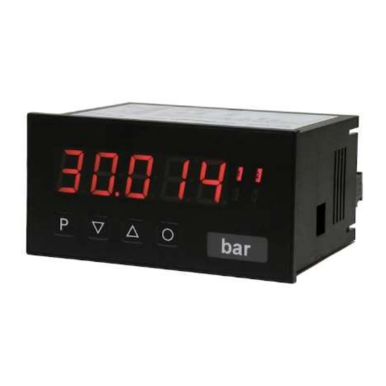
User manual M2
Alternating voltage / Alternating current signal rms-value (TRMS)
0-300 VAC, 0-600 VAC, 0-1 AAC, 0-5 AAC
Technical features:
• red display of -19999...99999 digits (optional: green, orange, blue)
• installation depth: 70 mm without plug-in terminal
• min/max-memory
• 30 adjustable supporting points
• display flashing at threshold value exceedance / undercut
• digital input for triggering of Hold, Tara
• permanent min/max value recording
• volume metering (totaliser)
• mathematical functions like reciprocal value, square roots, squaring or rounding
• setpoint generator
• sliding averaging
• brightness control
• programming interlock via access code
• protection class IP65 at the front
• pluggable screw terminal
• optional galvanic isolated digital input or analog output
• optional 2 relay outputs
• accessories: PC-based configuration kit PM-TOOL incl. CD and USB-adapter for devices
without keypad and for a simple adjustment of standard devices
M2_14HGB.pdf update: 28.05.2020
96x48
Advertisement
Table of Contents

Related Manuals for montwill M2


Summary of Contents for montwill M2
- Page 1 User manual M2 Alternating voltage / Alternating current signal rms-value (TRMS) 0-300 VAC, 0-600 VAC, 0-1 AAC, 0-5 AAC Technical features: • red display of -19999…99999 digits (optional: green, orange, blue) • installation depth: 70 mm without plug-in terminal • min/max-memory •...
- Page 2 AC current, AC voltage Housing size: 96x48 mm M2-1VR5B.0004.570xD Options – breakdown of order code: M 2- 1 V R 5 B. 0 H 0 4. 5 7 2 x D Basic type M2 Dimension D physical unit Installation depth 89mm Version incl.
-
Page 3: Table Of Contents
Contents 1. Brief description 2. Assembly 3. Electrical connection 4. Description of function and operation 4.1. Programming software PM-TOOL 5. Setting up the device 5.1. Switching on 5.2. Standard parameterisation (flat operation level) Value assignment for the triggering of the signal input 5.3. -
Page 4: Brief Description
1. Brief description 1. Brief description The panel meter instrument M2-14H is a 5-digit device for AC current / AC voltage signals (TRMS) and a visual threshold value monitoring via the display. The configuration happens via four keys at the front or by the optional PC software PM-TOOL. The integrated programming interlock prevents unrequested changes of parameters and can be unlocked again with an individual code. -
Page 5: Assembly
2. Assembly 2. Assembly Please read the Safety advices on page 32 before installation and keep this user manual for future reference. Gap for physical unit 1. After removing the fixing elements, insert the device. 2. Check the seal to make sure it fits securely. 3. -
Page 6: Electrical Connection
3. Electrical connection 3. Electrical connection Type M2-1VR5B.0H04.470xD with a supply of 115 VAC Type M2-1VR5B.0H04.570xD with a supply of 230 VAC 115 VAC Digital input 230 VAC (Option) 0-5 AAC 0...1 AAC 0-10 VDC 0/4-20 mA Analog output (Option) 0...300 VAC... -
Page 7: Description Of Function And Operation
4. Description of function and operation 4. Description of function and operation Operation The operation is divided into three different levels. Menu level (delivery status) This level is for the standard settings of the device. Only menu items which are sufficent to set the device into operation are displayed. - Page 8 4. Description of function and operation Function chart: 4.1 Parameterisation software PM-TOOL: Part of the PM-TOOL are the software on CD and an USB-cable with device adapter. The connection happens via a 4-pole micromatch-plug on the back side of the device, to the PC- side the connection happens via an USB plug.
-
Page 9: Setting Up The Device
5. Setting up the device 5. Setting up the device 5.1. Switching on Once the installation is complete, start the device by applying the voltage supply. Before, check once again that all electrical connections are correct. Starting sequence For 1 second during the switching-on process, the segment test ( ) is displayed followed by an indication of the software type and, after that, also for 1 second the software version. - Page 10 5. Setting up the device Menu level Parameterisation level Setting the start/offset value of the measuring range, Default: Enter the start/offset value from the smallest to the highest digit with [▲] [▼] and confirm each digit with [P]. After the last digit the display switches back to the menu level.
- Page 11 5. Setting up the device Menu level Parameterisation level Setting up the initial value of the analog output, Default: The final value is adjusted from the smallest digit to the highest digit with [▲] [▼] and digit by digit confirmed with [P]. A minus sign can only be parameterised on the highest digit.
-
Page 12: Programming Interlock
5. Setting up the device Menu level Parameterisation level User code (4-digit number-combination, free available), Default: If this code was set (>0000), all parameters are locked for the user, if has been selected before under menu item . By pressing [P] for 3 seconds in operation mode, the display shows . -
Page 13: Extended Parametersation (Professional Operation Level)
5. Setting up the device 5.4. Extended parameterisation (Professional operation level) 5.4.1. Signal input parameters Menu group level Menu level Menu level Parameterisation level Selection of the input signal, Default: There are several measuring input options: 0-600 VAC, 0-300 VAC or 0-5 AAC, 0- 1 AAC signals as works calibration (without application of the sensor signal) and as sensor calibration (with the sensor applied). - Page 14 5. Setting up the device Menu level Parameterisation level Setting the decimal point, Default: The decimal point on the display can be moved with [▲] [▼] and confirmed with [P]. The display then switches back to the menu level again. Setting up the display time, Default: then...
- Page 15 5. Setting up the device Menu level Parameterisation level Setting up the balance point, Default: The balance point for the final value can be chosen from the measuring range by with 0…300 V or with 0…1 A in %. The preset 80.000% result from the widespread detuning of the melt pressure sensors.
-
Page 16: General Device Parameters
5. Setting up the device Menu level Parameterisation level Device undercut, Default: With this function the device undercut ( ) can be defined on a definite value. Display overflow, Default: With this function the display overflow ( ) can be defined on a definite value. Back to menu group level, With [P] the selection is confirmed and the device changes into menu group level 5.4.2. - Page 17 5. Setting up the device Menu level Parameterisation level Rounding of display values, Default: This function is for instable display values, where the display value is changed in increments of 1, 5, 10 or 50. This does not affect the resolution of the optional outputs.
- Page 18 5. Setting up the device Menu level Parameterisation level Suppression of negative Offsets, Default: This function can be used to suppress negative display values. When ON, the function is active and all measured values below OFFS (measurand of initial value) are ignored, OFF is selected and negative numerical values are displayed, all measured values are linearized.
- Page 19 5. Setting up the device Menu level Parameterisation level Display, Default: With this function the current measurand, min/max value, totaliser value or the process-controlled Hold-value can be allocated to the display. With [P] the selection is confirmed and the device changes into menu level. Brightness control, Default: The brightness of the display can be adjusted in 16 levels from 00 = very dark to...
- Page 20 5. Setting up the device Menu level Parameterisation level Assignment (deposit) of key functions, Default: For the operation mode, special functions can be deposited on the navigation keys [▲] [▼], in particular this function is made for devices in housing size 48x24mm which do not have a 4th key ([O]-key).
- Page 21 5. Setting up the device Menu level Parameterisation level Special function [O]-key, Default: … For the operation mode, special functions can be deposited on the [O]-key. Activate this function by pressing the key. With the device is set temporarily on a parameterised value. The device acknowledges the correct taring with ooooo in the display.
-
Page 22: Safety Parameters
5. Setting up the device Menu level Parameterisation level Back to menu group level, With [P] the selection is confirmed and the device changes into menu group level 5.4.3. Safety parameters Menu group level Menu level Menu level Parameterisation level User code Default: Via this code reduced sets of parameters can be set free. -
Page 23: Analog Parameters
5. Setting up the device Menu level Parameterisation level Release/lock alarm parameters, Default: This parameter describes the user release/user lock of the alarm. : here only the range of value of the threshold values 1-4 can be changed : here the range of value and the alarm trigger can be changed all alarm parameters are released all alarm parameters are locked Back to menu group level,... - Page 24 5. Setting up the device Menu level Parameterisation level Selection analog output, Default: Three output signals are available 0-10 VDC, 0-20 mA and 4-20 mA. Select the desired signal with this function. Setting the final value of the analog output, Default: The final value is adjusted from the smallest to the highest digit with [▲] [▼] and confirmed digit per digit with [P].
-
Page 25: Relay Functions
5. Setting up the device 5.4.5. Relay functions Menu group level Menu level Menu level Parameterisation level Alarm relay 1, The same applies for relays 2-4 Default: …. …. Each setpoint (optional) can be linked up via 4 alarms (by default). This can either be inserted at activated alarms or deactivated alarms . - Page 26 5. Setting up the device Menu level Parameterisation level Logic relay 1, Default: Here, the switching behaviour of the relay is defined via a logic link, the following schema describes these functions with inclusion of . This parameter can only be selected if was selected under A1 v A2 As soon as a selected alarm is activated, the...
-
Page 27: Alarm Parameters
5. Setting up the device 5.4.6. Alarm parameters Menu group level Menu level Menu level Parameterisation level Depedency of alarm 1, Default: The dependency of alarm 1 can be related to special functions, in detail these are the current measurand, the min/max-value, the totaliser value/sum value, the sliding average value, the constant value or the difference between the current measurand and the constant value. - Page 28 5. Setting up the device Menu level Parameterisation level Function for threshold value undercut/exceedance, Default: A limit value undercut is selected with (for LOW = lower limit value), a limit value exceedance with (for HIGH = higher limit value). If e.g. limit value 1 is on a threshold level of 100 and allocated with function , an alarm is activated by reaching of the threshold level.
-
Page 29: Totaliser (Volume Metering)
5. Setting up the device 5.4.7. Totaliser (Volume metering) Menu group level Menu level Menu level Parameterisation level State of totaliser, Default: The totaliser realizes measurements on a time base of e.g. l/h, at this the scaled input signal is integrated by a time and steadily (select ) or temporarily (select ) saved. - Page 30 6. Reset to default values Menu level Parameterisation level Totaliser reset, Default: The reset value is adjusted from the smallest to the highest digit with the navigation keys [▲] [▼] and digit per digit confirmed with [P]. After the last digit, the display switches back to the menu level.
-
Page 31: Alarms / Relays
7. Alarms / Relays 7. Alarms / Relays This device has 4 virtual alarms that can monitor one limit value in regard of an undercut or exceedance. Each alarm can be allocated to an optional relay output S1-S2; furthermore alarms can be controlled by events like e.g. Hold or min/max-value. Function principle of alarms / relays Alarm / Relay x deactivated, instantaneous value, min/max-value, hold-value,... - Page 32 7. Alarms / Relays Quiescent current By quiescent current the alarm S1-S2 is on below the threshold and switched off on reaching the threshold. Switching-on delay The switching-on delay is activated via an alarm and e.g. switched 10 seconds after reaching the switching threshold, a short-term exceedance of the switching value does not cause an alarm, respectively does not cause a switching operation of the relay.
- Page 33 8. Sensor alignment offset / final value 8. Sensor alignment offset / final value The device is equipped with a semi-automatic sensor calibration ( ). A switching output operates the trimming resistor, which exists in some sensors. An adjustment of offset and final value takes place, after which the sensor can be used directly. Depending on parameterisation, the calibration can be realized via the 4th key or via the digital input.
-
Page 34: Technical Data
9. Technical data 9. Technical data Housing Dimensions 96x48x70 mm (BxHxD) 96x48x89 mm (BxHxD) incl. plug-in terminal Panel cut-out 92.0 +0.8 x 45.0 +0.6 Wall thickness up to 10 mm Fixing screw elements Material PC polycarbonate, black, UL94V-0 Sealing material EPDM, 65 Shore, black Protection class standard IP65 (front), IP00 (back side) - Page 35 9. Technical data Output Analog output 0/4-20 mA / burden 350 Ohm, 0-10 VDC / burden 10 kOhm, 16 bit Switching outputs Relay with change-over 250 VAC / 2 AAC; 30 VDC / 2 ADC contact 0.5 x 10 at contact load Switching cycles 0.5 x 10 mechanically...
-
Page 36: Safety Advices
Please inform the supplier immediately of any damage. Installation The M2-14H-device must be installed by a suitably qualified specialist (e.g. with a qualification in industrial electronics). Notes on installation •... -
Page 37: Error Elimination
11. Error elimination 11. Error elimination Error description Measures The unit permanently indicates • The input has a very high measurement, overflow. check the measuring circuit. • With a selected input with a low voltage signal, it is only connected on one side or the input is open. - Page 39 M2_14HGB.pdf update: 28.05.2020...
Need help?
Do you have a question about the M2 and is the answer not in the manual?
Questions and answers