Table of Contents
Advertisement
SECTION 1
1.1
Machine description ...............................................................................1-2
1.2
Planer/moulder major components ........................................................1-6
SECTION 2
2.1
Safety Symbols.......................................................................................2-1
2.2
Safety Instructions ..................................................................................2-1
SECTION 3
3.1
Planer/moulder setup ..............................................................................3-1
3.2
MP160 planer/moulder operation...........................................................3-3
SECTION 4
4.1
Wear life .................................................................................................4-1
4.2
Sawdust Removal ...................................................................................4-1
4.3
Miscellaneous Maintenance ...................................................................4-1
4.4
Drive Belt Tension Adjustment..............................................................4-2
4.5
Long-term storage ..................................................................................4-3
4.6
Safety Devices Inspection ......................................................................4-5
SECTION 5
5.1
Overall dimensions.................................................................................5-1
5.2
Specifications of the planer/moulder......................................................5-2
1-1
2-1
3-1
4-1
5-1
Advertisement
Table of Contents

Subscribe to Our Youtube Channel
Related Manuals for Wood-mizer MP160


Summary of Contents for Wood-mizer MP160
-
Page 1: Table Of Contents
Safety Symbols..................2-1 Safety Instructions ..................2-1 Planer/moulder operation Safety Labels Description SECTION 3 SETUP & OPERATION Planer/moulder setup ................3-1 MP160 planer/moulder operation............3-3 Control panel Planning / thicknessing Chain transmission with trapezoidal thread adjustment Variable speed motor manual SECTION 4 MAINTENANCE Wear life ....................4-1 Sawdust Removal ...................4-1... - Page 3 Wood-Mizer ® Safety, Setup, Operation and Maintenance MP160 E3S rev. A1.00 MP160 E3S-V rev. A1.00 Safety is our #1 concern! Read and understand all safety information and instructions before oper- ating, setting up or maintaining this machine. Form #2402 Original Instructions...
- Page 4 Safety Symbols..................2-1 Safety Instructions ..................2-1 Planer/moulder operation Safety Labels Description SECTION 3 SETUP & OPERATION Planer/moulder setup ................3-1 MP160 planer/moulder operation............3-3 Control panel Planning / thicknessing Chain transmission with trapezoidal thread adjustment Variable speed motor manual SECTION 4 MAINTENANCE Wear life ....................4-1 Sawdust Removal ...................4-1...
-
Page 5: Introduction
SECTION 1 INTRODUCTION Congratulations on your purchase of a Wood-Mizer Planer - Moulder! Wood-Mizer is committed to providing you with the latest technology, best quality, and strongest customer service available on the market today. We continually evaluate our customers’ needs to ensure we are meeting current wood-processing demands. -
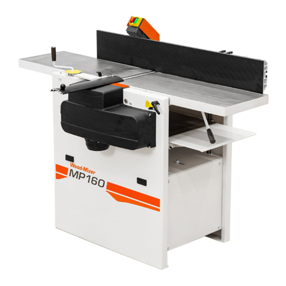
Page 6: Machine Description
All other uses of the planer are forbidden. The MP160 is a planer/moulder that can work two sides of a workpiece in one action. The planer/ moulder is contained in a stable and strong chassis. The planer/ moulder table is made of planed cast iron. - Page 7 The length required depends on the length of the workpieces you want to plane. The minimum length is 4 m (13 ft). Higher risk area 5 ft (1,5m) Outfeed 13 ft (4m) MP160 13 ft (4m) Infeed table table Control panel 5 ft (1,5m)
- Page 8 INTRODUCTION Machine description Allen wrench 4mm (supplied) Allen wrench 5 mm Allen wrench 6 mm Flat wrench 10 mm (supplied) Wrench 10 mm Box wrench 13 mm Flat wrench 30 mm (supplied) (for cutter) ...
- Page 9 Machine description CHIP EXTRACTOR MP160 planer/moulder must be connected to chip extractor with a capacity of at least 3 000m Remember that chip container has to be equipped with an air vent (e.g. a fine net or filter if dust are collected indoors).
-
Page 10: Planer/Moulder Major Components
Fence Handle for pushing material Top Table Height Adjustment Handle Emergency Switch Cutter with Top Table Height Safety Cover Scale Bottom Table Height Adjustment Crank Feed Rollers Drive Motor Table Height Scale Lockable Castors (optional) FIG. 1-1 MP160 doc121819 INTRODUCTION... -
Page 11: Safety
Safety Safety Symbols SECTION 2 SAFETY Safety Symbols The following symbols and signal words call your attention to instructions concerning your personal safety. Be sure to observe and follow these instructions. DANGER! indicates an imminently hazardous situation which, if not avoided, will result in death or serious injury. - Page 12 IMPORTANT! It is always the owner's responsibility to comply with all applicable federal, state and local laws, rules and regulations regarding the ownership and operation of your Wood-Mizer planer/moulder. Wood-Mizer planer/moulder...
- Page 13 Safety Safety Instructions Keep the Machine And Area Around Clean DANGER! Maintain a clean and clear path for all necessary movement around the planer/moulder and lumber stacking areas. Failure to do so will result in serious injury. Dispose of Sawing By-Products Properly ...
-
Page 14: Planer/Moulder Operation
Safety Planer/moulder operation DANGER! Always be aware of and take proper protective measures against rotating shafts, pulleys, fans, etc. Always stay a safe distance from rotating members and make sure that loose clothing or long hair does not engage rotating members resulting in possible injury. WARNING! Beware of rotating parts. - Page 15 Safety Planer/moulder operation When planing smaller material, it should be stiffened/extended, e.g. with a longer piece of wood. Never stand in front of the material being fed or received, because it may suddenly kickback uncontrollably towards the operator. This applies to both the in and outfeed sides, although the risk is higher on the infeed side.
- Page 16 Always be sure that all safety decals are clean and readable. Replace all damaged safety decals to prevent personal injury or damage to the equipment. Contact your local distributor or Wood-Mizer Customer Service to order more decals. IMPORTANT! If replacing a component which has a safety decal affixed to it, make sure the new component also has the safety decal affixed in the same place.
-
Page 17: Safety Labels Description
Safety Safety Labels Description Safety Labels Description See table below for safety labels description. TABELA 2-0 Label View Label Number Description 096317 CAUTION! Carefully read operator’s manual before handling the machine. Observe instructions and safety rules when operating. 099220 Close guards prior to operating the machine 099220 099221... - Page 18 Safety Safety Labels Description TABELA 2-0 096316 Electric box opening is possible with the switch in “0” position only. 096319 Always disconnect the power cord before opening the electric box. S12004G Always wear safety goggles when operating the planer/moulder! S12005G Always wear protective ear muffs when operating the planer/moulder! EGdoc121819...
- Page 19 Safety Safety Labels Description TABELA 2-0 501465 Always wear safety boots when operating the planer/moulder! 089296 Revolutions direction 089296 087649 Warning stripes 502481 P85070 CE safety certification Safety EGdoc121819...
-
Page 20: Setup & Operation
SETUP & OPERATION Planer/moulder setup SECTION 3 SETUP & OPERATION Planer/moulder setup IMPORTANT! Before starting to use the planer/moulder you have to meet the following conditions: Set up the planer/moulder on firm, level ground and level the planer/moulder. Secure the ... - Page 21 SETUP & OPERATION Planer/moulder setup IMPORTANT! It is recommended that a 30mA GFI (Ground Fault Interrupter) be used. IMPORTANT! When starting the machine for the first time, check that main motor rotation direction is as indicated by the arrow located on the motor body (fan guard).
-
Page 22: Mp160 Planer/Moulder Operation
MP160 planer/moulder operation MP160 planer/moulder operation 3.2.1 Control panel See figure 3-1. MP160 planer/moulder controls are shown below: FIG. 3-1 Top red button (A) - the emergency stop switch, which disconnects power to all functions. When the emergency stop switch is pressed, it must be released before restarting the planer/moulder (turn right). -
Page 23: Planning / Thicknessing
SETUP & OPERATION Planning / thicknessing 3.2.2 Planning / thicknessing DANGER! Before you remove any cover of the planer, ensure that the power is switched off and that the cutter are not rotating. WARNING! Use protective gloves, particularly when you need to loosen screws that are tightly fastened, or when you are tightening screws (see safety instructions). - Page 24 See figure 3-3. Fence (G) Angle Locking Fence Locking Pusher (D) Handles (H) Handle (I) Top Table Height Adjustment Handle(A) Protective Guard (E) Top Table Locking Handle (B) Top Table Height Scale (C) Guard Locking Handle (F) FIG. 3-3 MP160 EGdoc121819...
- Page 25 (K). Thicknessing depth can be adjust from 0,3 mm to 4 mm. The maximum depth can be set for the material width not bigger than 160mm. Always measure material and adjust the height before thicknessing. See figure 3-4. Bottom Table Height Adjustment Crank (J) Bottom Table Height Scale (K) FIG. 3-4 MP160 EGdoc121819...
- Page 26 SETUP & OPERATION Planning / thicknessing ADJUSTING OF THE OUTFEED TABLE Outfeed table is factory adjusted. However if this necessary to adjust the outfeed table it can be done with micro adjustment bolt (A-see below). The outfeed table should be adjusted so it is 0,02-0,05mm above the highest position of the knives.
- Page 27 SETUP & OPERATION Planning / thicknessing GRINDING THE PLANING KNIVES Always grind the knives in pairs, so they are the same height, min. 15 mm, otherwise vibrations could occur in the cutter. The grinding angle must be 38 degrees. ADJUSTING THE PLANING KNIVES Adjust planing knives (A) so they are on the same level with the outfeed table.
-
Page 28: Chain Transmission With Trapezoidal Thread Adjustment
SETUP & OPERATION Chain transmission with trapezoidal thread adjustment 3.2.3 Chain transmission with trapezoidal thread adjustment The chain used to raise and lower the table, must not be slack, but needs to be tensioned enough that teeth mesh correctly. The chain tension is adjusted with the nut located on the planer/moulder base, under the outfeed table. -
Page 29: Maintenance
MAINTENANCE Wear life SECTION 4 MAINTENANCE This section lists the maintenance procedures that need to be performed. CAUTION! Always disconnect and lock out power supply before performing any maintenance work, cleaning or servicing the planer/moulder. Failure to do so may result in serious injury. This symbol identifies the interval (hours of operation duty) at which each maintenance procedure should be performed. -
Page 30: Drive Belt Tension Adjustment
MAINTENANCE Drive Belt Tension Adjustment Feed roller drive chain Two slide rods and trapezoidal thread Cast iron table 4. Every 50 hours check that all screws and bolt connections are tightened. Check that cables and electrical connectors are in good condition. Drive Belt Tension Adjustment 4.4.1 Top cutter drive belt tension adjustment Check top cutter drive belt tension after first 20 hours of operation and every 50 hours of operation... -
Page 31: Roller Drive Chain Tension Adjustment
MAINTENANCE Long-term storage Using two chain tension adjustment bolts (C), adjust properly drive belt. Next tighten a motor plate mounting bolts. Mount cutter drive belt cover. 5. Check motor and cutter pulleys alignment. Both pulleys should be in line to avoid premature drive belt wear. - Page 32 MAINTENANCE Long-term storage Spray a thin layer of anti-rust coating (such as P.D.R.P) onto the places not protected against rusting. Store the machine in a well ventilated room. Cover the planer/moulder. doc121819 MAINTENANCE...
-
Page 33: Safety Devices Inspection
MAINTENANCE Safety Devices Inspection Safety Devices Inspection MP160E3S Moulder – Safety Devices Inspection Safety devices on the machine which must be checked before every shift: E-STOP button and its circuit inspection, 1. E-STOP button and its circuit inspection Use “I” buttons to start cutter and feed rollers. The motors should start. ... -
Page 34: Planer/Moulder Specifications
PLANER/MOULDER SPECIFICATIONS Overall dimensions SECTION 5 PLANER/MOULDER SPECIFICATIONS Overall dimensions See figure 5-1. The overall dimensions of the MP160 Planer/moulder are shown below (all dimensions in millimeters). FIG. 5-1 MP160 EGdoc121819 Specyfikacje... -
Page 35: Specifications Of The Planer/Moulder
PLANER/MOULDER SPECIFICATIONS Specifications of the planer/moulder See table 5-1. The overall dimensions and weight of MP160 are given in the table below. Planer/moulder type MP160 Weight 286 kg Weight with transport box 356 kg Height 1265 mm Width 964 mm... - Page 36 Motor Type Electric Motor Electric Motor Rated Voltage 3x400V 3x400V Rated revolutions 2860 r.p.m. 2820 r.p.m. Rated power 0,37 kW Wood-Mizer Part No. 533644 533642 Wood-Mizer Reducer Part ---- 533641 Wood-Mizer CVT Part No. ---- 533643 TABLE 5-4 EGdoc121819 Specyfikacje...
- Page 37 0,37 kW Wood-Mizer Part No. 533644 533642 Wood-Mizer Reducer Part ---- 533641 Wood-Mizer CVT Part No. ---- 533643 TABLE 5-4 See table 5-5. USA ECO motor specifications are given in the table below. MP160EC3U Top cutter motor Feed motor specifi-...
- Page 38 3x230V Rated revolutions 2820 r.p.m. Rated power 0,37 kW Wood-Mizer Part No. 533644-UL 533642-UL Wood-Mizer Reducer Part ---- 533641 Wood-Mizer CVT Part No. ---- 533643 TABLE 5-6 MP160EC3U-V Top cutter motor Feed motor specifi- specifications cations Motor Type Electric Motor...
- Page 39 MP160EH3S-V 2-12 m/min (Adjustable Feed Speed) TABLE 5-7 1 2 3 See table 5-8. The noise level generated by Wood-Mizer planer/moulder is given in the table below Noise Level Planer/Moulder MP160 = 102dB (A) Equipped with electric motor TABLE 5-8...
- Page 40 PLANER/MOULDER SPECIFICATIONS Specifications of the planer/moulder See table 5-10. Other specifications of the planer/moulder are listed below Cutter Specifications Number of knife sockets 2 or 4 Top cutter diameter 72 mm Top cutter width 410 mm Side cutter diameter 92 mm Side cutter width 40 mm Cutter adjustment...
- Page 41 PLANER/MOULDER SPECIFICATIONS Specifications of the planer/moulder See table 5-11. A relation between the pattern knife protrusion and the thickness is shown below. Pattern knife thickness Pattern knife max. protrusion 3 mm 13 mm 4 mm 21 mm 29 mm TABLE 5-11 According to EN 847-1:2005 European Standard Specyfikacje EGdoc121819...
- Page 42 EC declaration of conformity according to EC Machinery Directive 2006/42/EC, Annex II, 1.A Manufacturer: Wood-Mizer Industries sp. z o.o. Nagórna 114, 62-600 Koło; Poland Tel. +48 63 26 26 000 This declaration of conformity is issued under the sole responsibility of the manufacturer.
Need help?
Do you have a question about the MP160 and is the answer not in the manual?
Questions and answers