Table of Contents
Advertisement
Advertisement
Table of Contents

Related Manuals for Wood-mizer MP180 E6S


Summary of Contents for Wood-mizer MP180 E6S
- Page 3 Wood-Mizer ® Safety, Setup, Operation and Maintenance MP180 E6S rev. A1.01 MP180 E7S-V rev. A1.01 Safety is our #1 concern! Read and understand all safety information and instructions before oper- ating, setting up or maintaining this machine. Form #2406 Original Instructions...
-
Page 4: Table Of Contents
Table of Contest Section-Page SECTION 1 INTRODUCTION Machine Description ................1-2 Planer/moulder major components ............1-6 SECTION 2 SAFETY Safety Symbols..................2-1 Safety Instructions ..................2-1 SECTION 3 SETUP & OPERATION Multi-Planer Setup..................3-1 MP180 Multi-Planer Operation..............3-5 SECTION 4 MAINTENANCE Wear life ....................4-1 Sawdust Removal ...................4-1 Miscellaneous Maintenance ..............4-1 Drive Belt Tension Adjustment..............4-2 Long-Term Storage ................4-5... -
Page 5: Introduction
SECTION 1 INTRODUCTION Congratulations on your purchase of a Wood-Mizer Multi-Planer! Wood-Mizer is committed to providing you with the latest technology, best quality, and strongest customer service available on the market today. We continually evaluate our customers’ needs to ensure we are meeting current wood-processing demands. -
Page 6: Machine Description
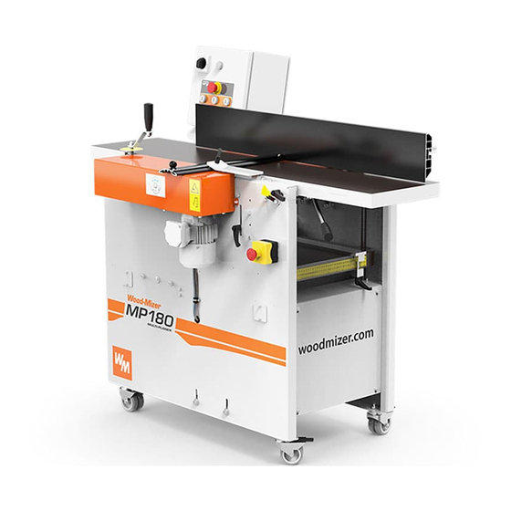
Machine Description The Wood-Mizer Multi-Planer is designed for straight and profiled planing of wooden elements used for production of wooden houses and other construction elements used in the building industry and garden programs. - Page 7 INTRODUCTION Machine Description MACHINE AND SITE PREPARATION The machine is delivered on a pallet. Due to the weight, it has to be transported with auxiliary carrier equipment and in accordance with the general safety rules. Check your Multi-Planer as soon as you receive it. Any transport damage must be reported to the transport company immediately.
- Page 8 INTRODUCTION Machine Description ANCHORING For the highest safety, the Multi-Planer must be anchored to the floor with 8-10 mm diameter anchor bolts. TOOLS REQUIRED TO USE THE MULTI-PLANER: Allen wrench 4 mm (supplied) Allen wrench 5 mm Allen wrench 6 mm ...
- Page 9 INTRODUCTION Machine Description 1 x 0.1 mm height (per cutter) These spacer rings are necessary to set the required height. CHIP EXTRACTOR The MP180 Multi-Planer must be connected to a chip extractor with a total capacity of at least 2 000m /h.
-
Page 10: Planer/Moulder Major Components
INTRODUCTION Planer/moulder major components Planer/moulder major components Electric box with Cutter with Fence control panel Chip Duct Safety Cover Handle for pushing material Top Table Height Adjustment Handle Emergency Switch Top Table Height Scale Table Height Scale Feed Rollers Drive Motor Bottom Table Height Adjustment Crank... -
Page 11: Safety
Safety Safety Symbols SECTION 2 SAFETY Safety Symbols The following symbols and signal words call your attention to instructions concerning your personal safety. Be sure to observe and follow these instructions. DANGER! indicates an imminently hazardous situation which, if not avoided, will result in death or serious injury. - Page 12 It is always the owner's responsibility to comply with all applicable federal, state and local laws, rules and regulations regarding the ownership and operation of your Wood-Mizer Multi-Planer. All Wood-Mizer Multi-Planer owners are encouraged to become thoroughly familiar with these applicable laws and comply with them fully while using the machine.
- Page 13 Safety Safety Instructions Keep the machine and area around clean. DANGER! Maintain a clean and clear path for all necessary movement around the Multi-Planer and lumber stacking areas. Failure to do so will result in serious injury. Dispose of sawing by-products properly. ...
- Page 14 Safety Multi-Planer Operation do not engage rotating members resulting in possible injury. WARNING! Beware of rotating parts. Shut down the machine and allow all moving parts to come to a complete stop before removing any guards and covers. Do NOT operate the Multi-Planer with any guards or covers removed.
- Page 15 Safety Multi-Planer Operation Never stand in front of the material being fed or received, because it may kickback suddenly towards the operator. This applies to both the infeed and outfeed sides, although the risk is higher on the infeed side. DANGER! Planing/moulding is possible only in the direction shown below.
- Page 16 Always be sure that all safety decals are clean and readable. Replace all damaged safety decals to prevent personal injury or damage to the equipment. Contact your local distributor or Wood-Mizer Customer Service to order more decals. IMPORTANT! If replacing a component which has a safety decal affixed to it, make sure the new component also has the safety decal affixed in the same place.
- Page 17 Safety Safety Labels Description Safety Labels Description See the table below for safety labels description. TABLE 2-0 Label View Label Number Description 096317 CAUTION! Carefully read the operator’s manual before operating the machine. Observe all instructions and safety rules when operating. 099220 Close all guards and covers prior to operating the machine.
- Page 18 Safety Safety Labels Description TABLE 2-0 096316 Do not open or close the electric box when the switch is not in the ”0” position. 096319 Always disconnect the power cord before opening the electric box. S12004G Always wear safety goggles when operating the Multi-Planer! S12005G Always wear protective ear muffs when...
- Page 19 Safety Safety Labels Description TABLE 2-0 501465 Always wear safety boots when operating the Multi-Planer! 510080 Always wear safety gloves when operating the Multi-Planer! S20097 Motor rotation direction P85070 CE safety certification510080 535252 Use the continuously variable transmission only when the feed is turned on. Safety EGdoc052521...
- Page 20 Safety Safety Labels Description TABLE 2-0 551139 Warning! The side cutter rotates for 10 seconds after the machine is shut-off. 551139 536401 Cutter rotation direction 2-10 EGdoc052521 Safety...
-
Page 21: Setup & Operation
SETUP & OPERATION Multi-Planer Setup SECTION 3 SETUP & OPERATION Multi-Planer Setup IMPORTANT! Before starting to use the Multi-Planer you have to meet the following conditions: Set up the Multi-Planer on firm, level ground and level the machine. Secure the planer to the ... - Page 22 SETUP & OPERATION Multi-Planer Setup See table 3-1. Have a qualified electrician install the power supply (according to EN 60204 Standard). The power supply must meet the specifications given below. 3-Phase Fused Disconnect Suggested Wire Size Volts Switch 400 VAC 16 A 1.5 mm Max.
- Page 23 SETUP & OPERATION Multi-Planer Setup See figure 3-2. FIG. 3-2 Mount the upper outfeed table using M8x25 socket head screws (A). Tighten the screws firmly. The adjusting screws (B) are factory-set and do not need to be adjusted. WARNING The outfeed table must be handled by two adult persons.
- Page 24 SETUP & OPERATION Multi-Planer Setup Review the safety instructions! Ensure that all cutters can rotate freely. Be sure the emergency stop button is released. Be sure the upper cover is closed and the limit switch is activated. Be sure all machine’s parts are ...
-
Page 25: Mp180 Multi-Planer Operation
SETUP & OPERATION MP180 Multi-Planer Operation MP180 Multi-Planer Operation 3.2.1 Control Panel See figure 3-4. The MP180 Multi-Planer controls are shown below. FIG. 3-4 Top red button (A) - the emergency stop button which disconnects power to all functions. When it is pressed, it must be released before restarting the Multi-Planer (turn right). - Page 26 SETUP & OPERATION Planning / Thicknessing 3.2.2 Planning / Thicknessing DANGER! Before you remove any cover of the planer, ensure that the power is switched off and the cutters are not rotating. WARNING! Use protective gloves, particularly when you need to loosen screws that are tightly fastened, or when you are tightening screws (see the safety instructions).
- Page 27 SETUP & OPERATION Planning / Thicknessing SETTING THE MACHINE FOR PLANING/THICKNESSING The top cutter is fixed to the housing and hung at both ends. Two planing knives are mounted in two cutter sockets (planer knife 410 mm HSS). The planing thickness is adjusted with the planing (top) table handle (A). After performing the ...
- Page 28 SETUP & OPERATION Planning / Thicknessing The thicknessing depth is adjusted with the crank (J). The set thickness can be read on the scale (K). The thicknessing depth can be adjusted from 0.3 mm to 4 mm. The maximum depth can be set for the material width not bigger than 160 mm.
- Page 29 SETUP & OPERATION Planning / Thicknessing ADJUSTING THE OUTFEED TABLE The outfeed table is factory adjusted. However, if it is necessary to adjust the outfeed table, it can be done with the micro adjustment bolt (A - see below). The outfeed table should be adjusted so it is 0.02 - 0.05 mm above the highest position of the knives.
- Page 30 SETUP & OPERATION Planning / Thicknessing GRINDING THE PLANING KNIVES Always grind the knives in pairs, so they are the same height, at least 15 mm, otherwise vibrations can occur in the cutter. The grinding angle must be 38 degrees. ADJUSTING THE PLANING KNIVES Adjust the planing knives (A) so they are at the same level with the outfeed table.
- Page 31 SETUP & OPERATION Side Cutter Review the safety instructions! 3.2.3 Side Cutter WARNING! Before you open the safety doors on the planer, ensure that the power is switched off and that the cutters are not rotating. side cutter rotates for 10 seconds after the machine is shut off. WARNING! Use protective gloves, particularly when you need to loosen screws that are tightly fastened, or when you are tightening...
- Page 32 SETUP & OPERATION Side Cutter Review the safety instructions! DISASSEMBLING Fixed cutter: Loosen the nut on the spindle with a 30 mm wrench (supplied) and a 13 mm wrench or adjustable wrench. Unscrew the nut and remove the cutter (A) and any spacing rings under the cutter.
- Page 33 If the knife profile is damaged, it should be ground again using a professional sharpener. This service is usually available in the nearby. If not, contact Wood-Mizer. EGdoc052521 3-13...
- Page 34 SETUP & OPERATION Chain transmission with trapezoidal thread adjustment 3.2.4 Chain transmission with trapezoidal thread adjustment The chain used to raise and lower the table must not be slack, but needs to be tensioned enough so that its teeth mesh correctly. The chain tension is adjusted with the nut located on the machine base, under the outfeed table.
-
Page 35: Maintenance
MAINTENANCE Wear life SECTION 4 MAINTENANCE This section lists the maintenance procedures that need to be performed. CAUTION! Always disconnect and lock out power supply before performing any maintenance work, cleaning or servicing the Multi-Planer. Failure to do so may result in serious injury. This symbol identifies the interval (hours of operation duty) at which each maintenance procedure should be performed. -
Page 36: Drive Belt Tension Adjustment
MAINTENANCE Drive Belt Tension Adjustment Feed roller drive chain, Two slide rods and trapezoidal thread, Cast iron table. 4. Every 50 hours check that all screws and bolt connections are tightened. Check that the cables and electrical connectors are in good condition. Drive Belt Tension Adjustment 4.4.1 Top cutter drive belt tension adjustment Check the top cutter drive belt tension after the first 20 hours of operation and every 50 hours of... - Page 37 MAINTENANCE Drive Belt Tension Adjustment 4. Using the belt tension adjustment bolts (D), adjust properly the drive belt. Next, tighten the motor plate mounting bolts. 5. Check if the motor and cutter pulleys are aligned. Both pulleys should be in line to avoid premature drive belt wear.
- Page 38 MAINTENANCE Drive Belt Tension Adjustment 4.4.3 Roller drive chain tension adjustment 1. Unbolt and remove the roller drive chain cover (A). 2. Loosen the tensioner bolt (B). Move the tensioner up/down to tension the chain properly. FIG. 4-3 doc052521 MAINTENANCE...
-
Page 39: Long-Term Storage
MAINTENANCE Long-Term Storage 4.4.4 Table chain tension adjustment Loosen two tension roller mounting bolts (A). Use the adjustment bolt B to adjust the table chain tension. A(2) FIG. 4-4 Long-Term Storage If the machine is not used for a long period of time, do as follows: Disconnect the power cord. -
Page 40: Safety Devices Inspection
MAINTENANCE Safety Devices Inspection Safety Devices Inspection MP180E7S Multi-Planer – Safety Devices Inspection Safety devices on the machine which must be checked before every shift: E-STOP button and its circuit inspection. 1. E-STOP buttons and their circuits inspection Use “I” buttons to start the cutter and feed rollers. The motors should start. ... - Page 41 MAINTENANCE Safety Devices Inspection Emergency Stop Button No. 1 Side Cutter Cover Emergency Stop Button No. 2 MAINTENANCE doc052521...
-
Page 42: Multi-Planer Specifications
MULTI-PLANER SPECIFICATIONS Overall Dimensions SECTION 5 MULTI-PLANER SPECIFICATIONS Overall Dimensions See figure 5-1. The overall dimensions of the MP180 Multi-Planer are shown below (all dimensions are in millimeters). FIG. 5-1 MP180 EGdoc052521 Specifications... - Page 43 1315 mm Width 954 mm Length 1401 mm TABLE 5-1 Multi-Planer Specifications See table 5-2. The Wood-Mizer Multi-Planer nomenclature is given in the table below. Volts MP180EA6S 1 ph 230V CE MP180EA6U 1 ph 230V UL MP180EH6S 3 ph 400V CE...
- Page 44 MULTI-PLANER SPECIFICATIONS Multi-Planer Specifications Rated Revolutions 2860 r.p.m. 2860 r.p.m. 2820 r.p.m. Rated Power 3 kW 0,37 kW Wood-Mizer Part No. 537386 537385 533639 TABLE 5-3 MP180EB7S-V Top Cutter Motor Feed Motor Specifi- Specifications cations Motor Type Electric Motor Electric Motor...
-
Page 45: Multi-Planer Specifications
MP180EH7S-V 2-11 m/min (Adjustable Feed Speed) TABLE 5-5 1 2 3 See table 5-6. The noise level generated by Wood-Mizer Multi-Planer is given in the table below Noise Level MP180 Multi-Planer = 86dB (A) equipped with electric motor = 104dB (A) TABLE 5-6 1. - Page 46 MULTI-PLANER SPECIFICATIONS Multi-Planer Specifications IMPORTANT! The total value of hand-arm vibration the operator may be exposed to does not exceed 2.5 m/s . The highest root mean square value of weighted acceleration to which the whole operator’s body is subjected does not exceed 0.5 m/s See table 5-7.
- Page 47 MULTI-PLANER SPECIFICATIONS Multi-Planer Specifications See figure 5-2. FIG. 5-2 See table 5-9. A relation between the pattern knife protrusion and the thickness is shown below. Pattern knife thickness Pattern knife max. protrusion 3 mm 13 mm 4 mm 21 mm 29 mm TABLE 5-9 According to EN 847-1:2005 European Standard...
- Page 48 EC declaration of conformity according to EC Machinery Directive 2006/42/EC, Annex II, 1.A Manufacturer: Wood-Mizer Industries sp. z o.o. Nagórna 114, 62- Tel. +48 63 26 26 000 This declaration of conformity is issued under the sole responsibility of the manufacturer.
Need help?
Do you have a question about the MP180 E6S and is the answer not in the manual?
Questions and answers