Table of Contents
Advertisement
Quick Links
Advertisement
Table of Contents

Related Manuals for Spectron spectrolab BM55-2U


Summary of Contents for Spectron spectrolab BM55-2U
- Page 1 User manual Pressure control panel BM55-2U 07/2020...
-
Page 2: Table Of Contents
Table of contents Spectron Gas Control Systems GmbH Table of contents 1 Introduction..............................2 Description..............................2.1 Intended use ............................2.2 Misuse ..............................2.3 Identification / label ..........................2.4 Environment............................2.4.1 Temperatures..........................2.4.2 Degree of cleanliness ........................ 2.4.3 Emissions........................... 2.5 Standards and laws .......................... - Page 3 Spectron Gas Control Systems GmbH Table of contents 8.4 Regular maintenance work and cleaning....................27 9 Repair ................................28 9.1 General information on repair work ...................... 28 9.2 Troubleshooting and fault rectification ....................29 10 Decommissioning and recommissioning ....................30 10.1 Decommissioning ..........................
-
Page 4: Introduction
1 Introduction This user manual is the original user manual for the Pressure control panel BM55-2U from Spectron Gas Control Systems GmbH (Fritz-Klatte-Str. 8, D-65933 Frankfurt), referred to as Spectron. The user manual is intended to facilitate correct and safe operation for the operating firm, and to warn against misuse. -
Page 5: Description
Spectron Gas Control Systems GmbH Description | 2 2 Description 2.1 Intended use The intended use of the Pressure control panel BM55-2U is the expansion of a gas from a gas source and the distribution of the gas with adjustable outlet pressure. -
Page 6: Environment
2 | Description Spectron Gas Control Systems GmbH Article description BM55-2U-200-10-M-M-… Inlet pressure P1 200 bar Outlet pressure P2 10 bar Gas type GAS TYPE 2.4 Environment 2.4.1 Temperatures Normal temperatures expected in a production area are assumed when operating the system: -20°C to +60°C. - Page 7 Spectron Gas Control Systems GmbH Description | 2 TRBS 1111, 2152, 3145, 3146 Technische Regeln Betriebssicherheit (Tech- nical Regulations on Operational Safety) DGUV Regulation 1 German Trade Association Principles of Pre- vention DGUV Rule 113-001 German Trade Association Rules on Explosion...
-
Page 8: Safety
3 | Safety Spectron Gas Control Systems GmbH 3 Safety 3.1 Basic information on the safety instructions The product complies with the recognised technical regulations. Nevertheless, knowledge of the media used and their dangers as well as basic knowledge of the pressure control panel are pre- requisites for safe and accident-free operation. -
Page 9: Safety Instructions
Spectron Gas Control Systems GmbH Safety | 3 3.2 Safety instructions The safety instructions are to be observed by all persons working on the system. The rules and regulations for accident prevention applicable to the place of use are to be observed. The in- struction of the operating and maintenance personnel on system safety must be documented. - Page 10 3 | Safety Spectron Gas Control Systems GmbH WARNING Repairs If the product is not used as intended, unpredictable operating conditions may occur. Serious personal injuries are possible. a) Repairs may not lead to a change in function. The system may not be tampered with or modified.
-
Page 11: Emergencies And Safety Devices
Spectron Gas Control Systems GmbH Safety | 3 NOTICE Transportation Persons may be injured while transporting the product. a) Always use suitable lifting equipment when lifting and moving heavy loads and ensure that the transport is secured correctly. NOTICE Lighting Incorrect switching actions or confusion can occur due to inadequate lighting. - Page 12 3 | Safety Spectron Gas Control Systems GmbH All operators, as well as personnel who regularly enter the area, must be trained on a minimum of the following topics: – Alarm rules at the site and conduct in the event of malfunctions and leaks –...
-
Page 13: Design And Function
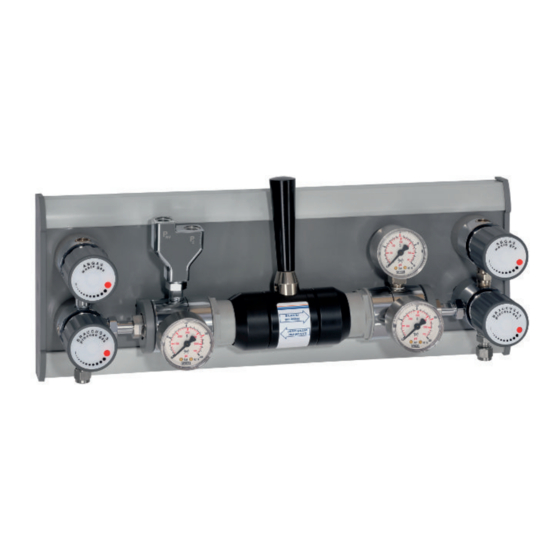
Spectron Gas Control Systems GmbH Design and function | 4 4 Design and function 4.1 Design Illustration of the pressure control panel with gas cylinder connected Illustration 1: Pressure control panel design BM55-2U Pos. Designation Short name Connection Process gas source valve Cylinder connection incl. -
Page 14: Functional Description
4 | Design and function Spectron Gas Control Systems GmbH 4.2 Functional description Waste gas Process gas Waste gas Waste gas Process gas Process gas Illustration 2: P&ID BM55-2U The intended use of the Pressure control panel BM55-2U is the expansion of a gas from a gas source and the distribution of the gas with adjustable outlet pressure. -
Page 15: Technical Data
(incl. power supply) are the connec- tions on the pressure control panel or product. The following areas and functions have not been included in the scope of supply from Spectron: – other systems, lines and installations of the overall system –... -
Page 16: Installation
5 | Installation Spectron Gas Control Systems GmbH 5 Installation 5.1 General information CAUTION Injury or damage in the event of incorrect assembly or disassembly Special steps are required for assembly and disassembly work on the product. Personal injuries and damage to the product are possible. - Page 17 The following applies to the Spectron compression fit- tings provided: Insert pipes up to the end stop into the threaded fit- tings and tighten union nut by 1 ¼...
-
Page 18: Connecting The Incoming And Outgoing Lines
5 | Installation Spectron Gas Control Systems GmbH 5.2.2 Connecting the incoming and outgoing lines All lines must be connected in accordance with the applicable standards and specifications and tested with purge gas (pressure test and leak test). The specifications on dimensioning of the connections are described in the "Design [} 13]"... - Page 19 Spectron Gas Control Systems GmbH Installation | 5 4. Close valve PGI. 5. Disassemble the leak test device and connect the exhaust gas line to valve HPV. 6. Relieve the pressure regulator. 7. Close all valves. The system should now be filled with inert gas (approx. 1 bar overpressure) up to the consumer.
-
Page 20: Commissioning
Connect the pig tails. Proceed as described in the instructions for use for the respective pig tail. The compression fitting of Spectron pig tails is pre-installed at the factory. Insert the end of the pipe with the union nut into the thread fitting of the process gas valve as far as it will go. -
Page 21: Flushing In The Process Gas To The Process
Spectron Gas Control Systems GmbH Commissioning | 6 6.2.2 Flushing in the process gas to the process Flushing in the entire line network to the consumer must be implemented via a waste gas valve on the process. To do this, refer to the system documentation for the consumer. This procedure does not apply to fluorine or fluorine mixtures. -
Page 22: Operation
"Decommissioning and recommissioning [} 30]" chapter. Valve HPI is controlled via the operating firm's controller (optional for SP3, SP4 and BM/ BE). This is not included in the delivery scope of Spectron and is therefore not covered in this user manual. - Page 23 Spectron Gas Control Systems GmbH Operation | 7 WARNING Gas source exchange If a gas source exchange is performed incorrectly, gas leakage and poisoning of persons may occur. a) The gas source exchange are to be carried out by trained specialist personnel and never unattended.
- Page 24 7 | Operation Spectron Gas Control Systems GmbH 4. Screw the process gas connection onto the gas source valve by hand and tighten it gastight with a spanner. 5. Open the process gas source valve, build up pressure, and close it again. Check using leak test spray whether the process gas port is leak-tight.
-
Page 25: Maintenance, Cleaning And Repairs
Spectron Gas Control Systems GmbH Maintenance, cleaning and repairs | 8 8 Maintenance, cleaning and repairs 8.1 General information on maintenance WARNING Noise emission When working on pressurised pneumatic supply, significant noise emission can occur. Acute and chronic loss of hearing may result. -
Page 26: Flushing The Process Gas Into The Pressure Control Panel
8 | Maintenance, cleaning and repairs Spectron Gas Control Systems GmbH CAUTION Injury or damage in the event of incorrect assembly or disassembly Special steps are required for assembly and disassembly work on the product. Personal injuries and damage to the product are possible. -
Page 27: Adjusting The Operating Pressure
Spectron Gas Control Systems GmbH Maintenance, cleaning and repairs | 8 8.3 Adjusting the operating pressure The pressure control panel is set at the factory to a specific nominal operating pressure or aver- age pressure (with the switching lever positioned in the middle). If necessary, this pressure can be changed: 1. -
Page 28: Repair
9 | Repair Spectron Gas Control Systems GmbH 9 Repair 9.1 General information on repair work WARNING Noise emission When working on pressurised pneumatic supply, significant noise emission can occur. Acute and chronic loss of hearing may result. a) Never perform work on the pressurised pneumatic supply without hearing protection. -
Page 29: Troubleshooting And Fault Rectification
Spectron Gas Control Systems GmbH Repair | 9 Detect and assess causes of malfunction Rectify faults and restore operational readiness Repairs to the product may only be performed by the manufacturer or specialist personnel in- structed on the system. Work on electrical system parts may only be performed by a qualified electrician. -
Page 30: Decommissioning And Recommissioning
10 | Decommissioning and recommissioning Spectron Gas Control Systems GmbH 10 Decommissioning and recommissioning 10.1 Decommissioning The gas supply via the pressure control panel can be interrupted without additional risks. If the pressure control panel remains unused or disassembled for an extended period, a decommis- sioning process must be carried out. -
Page 31: Dismantling And Disposal
Spectron Gas Control Systems GmbH Dismantling and disposal | 11 11 Dismantling and disposal 11.1 General information on dismantling WARNING Noise emission When working on pressurised pneumatic supply, significant noise emission can occur. Acute and chronic loss of hearing may result. -
Page 32: Returns
Spectron Gas Control Systems GmbH 11.2 Returns If products are returned to Spectron for checking, maintenance or repair, it is essential to purge them with inert gas (see also "Flushing through to the process"). A check can only be under- taken by Spectron if the decontamination declaration (https://www.spectron.de/sites/default/... - Page 33 Spectron Gas Control Systems GmbH Fritz-Klatte-Str. 8 D-65933 Frankfurt Tel: +49 (0)69 38016-0 Fax: +49 (0)69 38016-200 info@spectron.de www.spectron.de...
Need help?
Do you have a question about the spectrolab BM55-2U and is the answer not in the manual?
Questions and answers