Sign In
Upload
Download
Table of Contents
Contents
Add to my manuals
Delete from my manuals
Share
URL of this page:
HTML Link:
Bookmark this page
Add
Manual will be automatically added to "My Manuals"
Print this page
×
Bookmark added
×
Added to my manuals
Manuals
Brands
ASTRO Manuals
Amplifier
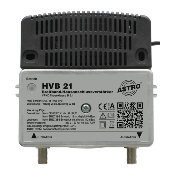
HVB 21
Operating manual
ASTRO HVB 21 Operating Manual
Broadband amplifires
Hide thumbs
1
2
Table Of Contents
3
4
5
6
7
8
9
10
11
12
13
14
15
16
17
18
19
20
page
of
20
Go
/
20
Contents
Table of Contents
Troubleshooting
Bookmarks
Table of Contents
Table of Contents
Symbols and Conventions Used
Intended Use
Intended Audience for this Manual
Device Description
Important Safety Information
Warranty Conditions
Performance Description
Disposal
Installation
Connection and Start-Up
Configuration
Troubleshooting
Maintenance and Repair
Block Diagram
Technical Data
Advertisement
Quick Links
Download this manual
Version 01-2021A
Table of
Contents
Previous
Page
Next
Page
1
2
3
4
5
Advertisement
Table of Contents
Need help?
Do you have a question about the HVB 21 and is the answer not in the manual?
Ask a question
Questions and answers
Related Manuals for ASTRO HVB 21
Amplifier ASTRO HVC 32 Operating Manual
Broadband amplifiers (20 pages)
Amplifier ASTRO HVC 42 Operating Manual
Broadband amplifiers (20 pages)
Amplifier ASTRO HVO V40 P Operating Manual
Universal broadband amplifier (24 pages)
Amplifier ASTRO HVB 31 Operating Manual
Broadband amplifires (20 pages)
Amplifier ASTRO HVB 32 Operating Manual
Broadband amplifires (20 pages)
Amplifier ASTRO HV 433-85 Vario Operating Manual
Broadband amplifier (24 pages)
Amplifier ASTRO HV 433-65 Vario Operating Manual
Broadband amplifiers (24 pages)
Amplifier ASTRO MIXAMP PRO Quick Start Manual
Pc/mac/playstation 4 (2 pages)
Amplifier ASTRO MixAmp Pro TR Quick Start Manual
Xbox one edition (2 pages)
Amplifier ASTRO VARIO 561 O Manual
Universal broadband amplifiers (28 pages)
Amplifier ASTRO MixAmp Pro TR Quick Start Manual
Ps4 edition (2 pages)
Amplifier ASTRO MIXAMP PRO TR Quick Start Manual
(2 pages)
Amplifier ASTRO U-911 User Manual
Active sat distribution field (12 pages)
Amplifier ASTRO TR MIXAMP PRO Quick Start Manual
(2 pages)
Amplifier ASTRO PA-1853 Instruction Manual
32ch multi-channel power amplifier (69 pages)
Amplifier ASTRO VARIO 561 F Operating Manual
Universal broadband amplifiers (32 pages)
This manual is also suitable for:
Hvb 31
Hvb 32
Table of Contents
Print
Rename the bookmark
Delete bookmark?
Delete from my manuals?
Login
Sign In
OR
Sign in with Facebook
Sign in with Google
Upload manual
Upload from disk
Upload from URL


Need help?
Do you have a question about the HVB 21 and is the answer not in the manual?
Questions and answers