Table of Contents
Advertisement
Quick Links
Advertisement
Table of Contents

Related Manuals for ASTRO HVO V40 P


Summary of Contents for ASTRO HVO V40 P
- Page 1 Version 01-2021A...
- Page 2 A PDF version of this manual can be downloaded on the ASTRO website (there may be a more recent version). The ASTRO company confirms that the information in this...
-
Page 3: Table Of Contents
Connection and start-up............page 14 Configuring the forward path..........page 14 Configuring the return path...........page 16 Measurements..............page 17 Troubleshooting..............page 18 Maintenance and repair............page 18 Block diagram..............page 19 Technical data..............page 20 Drilling distances..............page 22 Operating manual HVO V40 P - Version 01-2021A page 3... -
Page 4: Symbols And Conventions Used
Used batteries must be disposed of at approved recycling points. Batteries must be completely discharged before disposal. This symbol indicates components which must not be disposed of with household rubbish. page 4 Operating manual HVO V40 P - Version 01-2021A... -
Page 5: Intended Use
Intended use Intended use The HVO V40 P amplifier is a universal broadband amplifier for bidi- rectional building distribution and broadband communication systems. It is exclusively designed for signal amplification in unidi- rectional and bidirectional distribution systems in single-family and multi-family dwellings. -
Page 6: Device Description
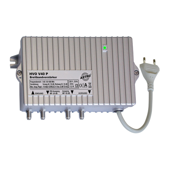
[2] Earth terminal [3] Power cable [4] Output [5] Output test socket [6] Return path output test socket [7] Input [8] Screw mount for housing cover Fig. 1: HVO V40 P amplifier page 6 Operating manual HVO V40 P - Version 01-2021A... - Page 7 [13] Input test socket (bidirectional) Fig. 2: HVO V40 P amplifier, interior view The HVO V40 P amplifier has a CE marking. This confirms that the product complies with the relevant EC directives and adheres to the requirements specified therein.
-
Page 8: Important Safety Information
A PDF version of this manual can be downloaded on the ASTRO website (there may be a more recent version). Check the packaging and the device for transport damage immediately. - Page 9 The device is operational when connected to the mains voltage. Operating manual HVO V40 P - Version 01-2021A page 9...
- Page 10 During operation, the device must always be covered by the components provided for this purpose. It is not permitted to operate the device when the cover is open. page 10 Operating manual HVO V40 P - Version 01-2021A...
- Page 11 They may also cause device malfunctions. Do not connect the supplied mains adapter to any other prod- ucts. Operating manual HVO V40 P - Version 01-2021A page 11...
-
Page 12: Warranty Conditions
Instructions regarding the necessary protec-tive measures to prevent electrostatic discharges in the device according to DIN EN 61340-5-1 must be observed! The HVO V40 P amplifier can be flexibly configured for future multi- media cable networks: Adjustment of gain in the forward and return paths using jumpers ... -
Page 13: Disposal
After use, this device must be disposed of in an orderly manner as electronic scrap, in accordance with the current disposal regula- tions of your district/country/state. ASTRO Strobel is a member of the Elektro system solution for the disposal of packaging materials. Our contract number is 80395. Installation... -
Page 14: Connection And Start-Up
0 dB pads are inserted in all other slots ATTENTION The maximum operating level must not be exceeded! (maximum input level = output level minus the set gain for 862 MHz) page 14 Operating manual HVO V40 P - Version 01-2021A... - Page 15 Remove the housing cover by loosening both screws [7] (see picture above left). The HVO V40 P amplifier has an attenuator and pad [1] in the forward path, as well as a tilt equaliser [2] and a cable attenu- ation simulator [3] and pad (see left). Important: To...
-
Page 16: Configuring The Return Path
[12], both sides of the diplex filter in the return path range are terminated with 75 Ω! The pads in the return path range must be removed in the process! page 16 Operating manual HVO V40 P - Version 01-2021A... -
Page 17: Measurements
After configuring the amplifier and completing the measurements, it is strongly recommended to terminate both test sockets with FUR 75 terminating resistors to ensure operation in compliance with the standards. Operating manual HVO V40 P - Version 01-2021A page 17... -
Page 18: Troubleshooting
Check whether the output level on the device is within the permissible limits for the operating level. If the problem cannot be resolved, please contact ASTRO customer service. Maintenance and repair ATTENTION It is essential that the following safety infor-mation be observed when performing maintenance and repair work. -
Page 19: Block Diagram
Block diagram Block diagram Operating manual HVO V40 P - Version 01-2021A page 19... -
Page 20: Technical Data
UMKBW Certification cascaded operation Mounting and operation heigth < 2000 m over N.N. Supply voltage [V~/Hz] 230 / 50 Power consumption [VA] / [W] 28 / 12,5 accord. EN 50083 -2 page 20 Operating maual HVO V40 P - Version 01-2021A... - Page 21 Technical data Ambient temperature [°C] -15…+55 Housing (W x H x D) [mm] 210 x 120 x 66 Weight [kg] Operating manual HVO V40 P - Version 01-2021A page 21...
-
Page 22: Drilling Distances
Drilling distances Drilling distances page 22 Operating maual HVO V40 P - Version 01-2021A... - Page 23 Drilling distances Operating manual HVO V40 P - Version 01-2021A page 23...
- Page 24 Internet: www.astro-kom.de All the information contained in this document has been checked in good faith. The ASTRO company cannot be held liable for any damage or injury arising in connection with the use of these operating instructions. Operating manual...
Need help?
Do you have a question about the HVO V40 P and is the answer not in the manual?
Questions and answers