Table of Contents
Advertisement
Quick Links
Advertisement
Table of Contents

Related Manuals for ASTRO VARIO 561 F


Summary of Contents for ASTRO VARIO 561 F
- Page 1 Version 01-2021A...
- Page 2 2 Operating manual VARIO 561 F, 662 F, 683 F, 684 F - Version 01-2021A...
-
Page 3: Table Of Contents
Configuring the return path...........page 21 Measurements..............page 22 Start-up................page 22 Troubleshooting..............page 23 Maintenance and repair............page 23 Block diagram..............page 24 Technical data..............page 25 Drilling distances..............page 31 Operating manual VARIO 561 F, 662 F, 683 F, 684 F - Version 01-2021A page 3... -
Page 4: Symbols And Conventions Used
Used batteries must be disposed of at approved recycling points. Batteries must be completely discharged before disposal. This symbol indicates components which must not be disposed of with household rubbish. page 4 Operating manual VARIO 561 F, 662 F, 683 F, 684 F - Version 01-2021A... -
Page 5: Intended Use
Intended use Intended use The VARIO 561 F, 662 F, 683 F and 684 F amplifiers are universal broadband amplifiers for bidirectional building distribution and broadband communication systems. It is exclusively designed for signal amplification in unidirectional and bidirectional distribution systems in single-family and multi-family dwellings. -
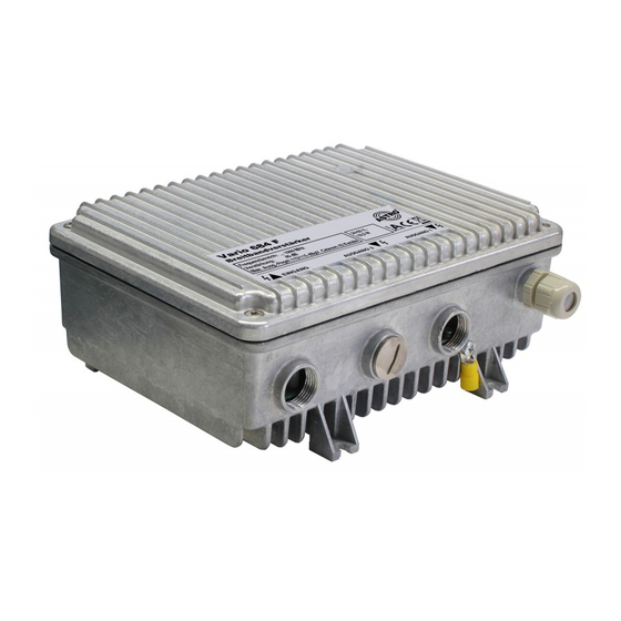
Page 6: Device Description
Device description Device description The device packaging contains the following: VARIO 561 F, 662 F, 683 F and 684 F broadband amplifiers 0 dB pads for device configuration, inserted 2 zero cards of type VZ 1001, inserted ... - Page 7 [18] Optional diplex filter [19] Input test socket The VARIO 561 F, 662 F, 683 F and 684 F amplifiers have a CE marking. This confirms that the products comply with the relevant EC directives and adhere to the requirements specified therein.
-
Page 8: Important Safety Information
An installation site must be provided that prevents children from playing with the device and its connections. The electrical connection conditions must correspond to the specifications on the device type plate. page 8 Operating manual VARIO 561 F, 662 F, 683 F, 684 F - Version 01-2021A... - Page 9 The device is operational when connected to the mains voltage. Operating manual VARIO 561 F, 662 F, 683 F, 684 F - Version 01-2021A page 9...
- Page 10 During operation, the device must always be covered by the components provided for this purpose. It is not permitted to operate the device when the cover is open. page 10 Operating manual VARIO 561 F, 662 F, 683 F, 684 F - Version 01-2021A...
- Page 11 They may also cause device malfunctions. Do not connect the supplied mains adapter to any other prod- ucts. Operating manual VARIO 561 F, 662 F, 683 F, 684 F - Version 01-2021A page 11...
-
Page 12: Information About Supplying Power Remotely
H03VV-U 2x 0.75 mm , minimum diameter 5 mm H03VV-K 2x 0.75 mm , minimum diameter 5 mm (F: flexible, U: rigid, K: finely stranded, fixed) page 12 Operating manual VARIO 561 F, 662 F, 683 F, 684 F - Version 01-2021A... - Page 13 If power is supplied via the coaxial connectors, the corresponding remote power supply fuse in the power supply unit can remain in- serted. Operating manual VARIO 561 F, 662 F, 683 F, 684 F - Version 01-2021A page 13...
- Page 14 (i.e. a radius of 2.5 m) must be ensured. In order to achieve this, all conducting parts must be connected with the device with a copper conductor of at least 4 mm page 14 Operating manual VARIO 561 F, 662 F, 683 F, 684 F - Version 01-2021A...
-
Page 15: Warranty Conditions
The general terms and conditions of ASTRO Strobel GmbH apply. They can be found in the current catalogue or on the Internet under “www.astro-kom.de”. Operating manual VARIO 561 F, 662 F, 683 F, 684 F - Version 01-2021A page 15... -
Page 16: Performance Description
The VARIO 561 F PG11, 662 F PG11, 681 F PG11, 682 F PG11 and 684 F PG11 amplifiers can be flexibly configured for future multimedia cable networks: ... -
Page 17: Disposal
First, screw the desired adapters (see page 3) or the cable fitting with PG11 thread onto the input and output connections of the am- plifier. Operating manual VARIO 561 F, 662 F, 683 F, 684 F - Version 01-2021A page 17... - Page 18 [3]. ESULT The device is now fitted with input and output sockets and can be connected. page 18 Operating manual VARIO 561 F, 662 F, 683 F, 684 F - Version 01-2021A...
-
Page 19: Connection
[2] to power the device locally. ESULT The device is now ready for operation. The power indicator [1] (see picture bottom left) lights up. Operating manual VARIO 561 F, 662 F, 683 F, 684 F - Version 01-2021A page 19... -
Page 20: Configuring The Forward Path
Configuring the forward path REPARATION VARIO 561 F, 662 F, 683 F and 684 F equalisers have an input equaliser and pad in the forward path to equalise incoming cable at- tenuation [1], as well as an inverse input equaliser and pad to sim- ulate cable attenuation [2] (see above left). -
Page 21: Configuring The Return Path
Adjust the input attenuation in the return path by inserting the corresponding pad [7] (see bottom left). ESULT The device is now configured for the transmission of return signals. Operating manual VARIO 561 F, 662 F, 683 F, 684 F - Version 01-2021A page 21... -
Page 22: Measurements
Measurements Measurements The VARIO 561 F, 662 F, 683 F and 684 F amplifiers have 4 test sockets. At the input, there is a bidirectional test socket [16] (see picture left) with 20 dB decoupling attenuation, which you can use to measure the input level for the forward path and the output level for the return path. -
Page 23: Troubleshooting
The device may need to be sent to the manufac- turer. Operating manual VARIO 561 F, 662 F, 683 F, 684 F - Version 01-2021A page 23... -
Page 24: Block Diagram
Block diagram Block diagram page 24 Operating manual VARIO 561 F, 662 F, 683 F, 684 F - Version 01-2021A... -
Page 25: Technical Data
[dB] ≥ 18 (> 14 MHz -1,5 dB/Octave) In-/Outputs & Testpoints accord. EN 50083-2 Protection class IP 54, categorie 2 accord. DIN EN 60529 Operating manual VARIO 561 F, 662 F, 683 F, 684 F - Version 01-2021A page 25... - Page 26 [mm] 204 x 73 x 150 Weight [kg] Return loss [dB] ≥ 18 (> 14 MHz -1,5 dB/Octave) In-/Outputs & Testpoints accord. EN 50083-2 page 26 Operating manual VARIO 561 F, 662 F, 683 F, 684 F - Version 01-2021A...
- Page 27 5 - 33 MHz / 47 - 862 5 - 65 MHz / 80 - 1000 Only the VD 65 diplex filter can be used with the VARIO 684. Operating manual VARIO 561 F, 662 F, 683 F, 684 F - Version 01-2021A page 27...
- Page 28 Drilling distances Drilling distances page 28 Operating manual VARIO 561 F, 662 F, 683 F, 684 F - Version 01-2021A...
- Page 29 Drilling distances Operating manual VARIO 561 F, 662 F, 683 F, 684 F - Version 01-2021A page 29...
- Page 30 Drilling distances page 30 Operating manual VARIO 561 F, 662 F, 683 F, 684 F - Version 01-2021A...
-
Page 31: Drilling Distances
Drilling distances Operating manual VARIO 561 F, 662 F, 683 F, 684 F - Version 01-2021A page 31... - Page 32 Internet: www.astro-kom.de All the information contained in this document has been checked in good faith. The ASTRO company cannot be held liable for any damage or injury arising in connection with the use of these operating instructions. operating manual VARIO 561 F, 662 F, 683 F, 684 F -...
Need help?
Do you have a question about the VARIO 561 F and is the answer not in the manual?
Questions and answers