Table of Contents
Advertisement
Quick Links
Advertisement
Table of Contents

Related Manuals for ASTRO HVC 32


Summary of Contents for ASTRO HVC 32
- Page 1 Version 01-2021A...
- Page 2 A PDF version of this manual can be downloaded on the ASTRO website (there may be a more recent version). The ASTRO company confirms that the information in this...
-
Page 3: Table Of Contents
Warranty conditions.............page 12 Performance description............page 12 Disposal................page 13 Installation................page 13 Connection and start-up............page 14 Configuration...............page 14 Measurements..............page 16 Troubleshooting..............page 17 Maintenance and repair............page 17 Block diagrams..............page 18 Technical data..............page 18 Operating manual HVC 32 a. HVC 42 - Version 01-2021A page 3... -
Page 4: Symbols And Conventions Used
Used batteries must be disposed of at approved recycling points. Batteries must be completely discharged before disposal. This symbol indicates components which must not be disposed of with household rubbish. page 4 Operating manual HVC 32 a. HVC 42 - Version 01-2021A... -
Page 5: Intended Use
Intended use Intended use The HVC 32 and HVC 43 are universal broadband amplifiers for bidirectional building distribution and broadband communication systems. They are exclusively designed for signal amplification in unidirectional and bidirectional distribution systems in single-family and multi-family dwellings. -
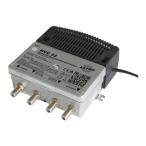
Page 6: Device Description
Device description Device description The device packaging contains the following: Building broadband amplifier HVC 32, or HVC 42 Jumpers for device configuration (pre-assembled) 2 screws and wall plugs 2x terminating resistors FUR 75 (for terminating the test sockets) ... - Page 7 Fig. 2: HVC 42 amplifier, interior view (HVC 32 identical) The HVC 32 and HVC 42 amplifiers have a CE-marking. This confirms that the products comply with the relevant EC directives and adhere to the requirements specified therein.
-
Page 8: Important Safety Information
A PDF version of this manual can be downloaded on the ASTRO website (there may be a more recent version). Check the packaging and the device for transport damage immediately. - Page 9 The device is operational when connected to the mains voltage. Operating manual HVC 32 a. HVC 42 - Version 01-2021A page 9...
- Page 10 During operation, the device must always be covered by the components provided for this purpose. It is not permitted to operate the device when the cover is open. page 10 Operating manual HVC 32 a. HVC 42 - Version 01-2021A...
- Page 11 They may also cause device malfunctions. Do not connect the supplied mains adapter to any other prod- ucts. Operating manual HVC 32 a. HVC 42 - Version 01-2021A page 11...
-
Page 12: Warranty Conditions
In order to use the device properly, you must carefully read the following safety and operating instructions. The HVC 32 and 43 amplifiers can be flexibly configured for future multimedia cable networks: Adaptation of local level conditions using the adjustable built-in attenuator and equaliser in the input ... -
Page 13: Installation
Screw the device in place using wood screws or sheet metal screws (drill holes [5] in the device, see left). ESULT The module is now installed and can be connected. Operating manual HVC 32 a. HVC 42 - Version 01-2021A page 13... -
Page 14: Connection And Start-Up
This setting must not be changed in networks that do not use a return path! page 14 Operating manual HVC 32 a. HVC 42 - Version 01-2021A... - Page 15 [6] is screwed in (see picture left) and must be set according to the required cable pre-equalisation or post-equal- isation. ESULT The device is now configured for the transmission of return signals. Operating manual HVC 32 a. HVC 42 - Version 01-2021A page 15...
-
Page 16: Measurements
After configuring the amplifier and completing the measurements, it is strongly recommended to terminate both test sockets with FUR 75 terminating resistors to ensure operation in compliance with the standards. page 16 Operating manual HVC 32 a. HVC 42 - Version 01-2021A... -
Page 17: Troubleshooting
Check whether the output level on the device is within the permissible limits for the operating level. If the problem cannot be resolved, please contact ASTRO customer service. Maintenance and repair ATTENTION It is essential that the following safety infor-mation be observed when performing maintenance and repair work. -
Page 18: Block Diagrams
Block diagram Block diagram 0 / 6 dB 0 / 7 dB 0..15 dB 0..15 dB 0..15 dB 0..10 dB TP -20 dB TP -20 dB page 18 Operating manual HVC 32 a. HVC 42 - Version 01-2021A... -
Page 19: Technical Data
Mounting and operation height < 3000 m über N.N. Protection Class DIN EN 60 529-IP 20 *) at 85 - 109 MHz with bandwidth conversion; **) measured at 10 MHz Operating manual HVC 32 a. HVC 42 - Version 01-2021A page 19... - Page 20 Internet: www.astro-kom.de All the information contained in this document has been checked in good faith. The ASTRO company cannot be held liable for any damage or injury arising in connection with the use of these operating instructions. Operating manual HVC 32 a.
Need help?
Do you have a question about the HVC 32 and is the answer not in the manual?
Questions and answers