Table of Contents
Advertisement
Quick Links
Advertisement
Table of Contents

Related Manuals for Airflow Adroit DV245


Summary of Contents for Airflow Adroit DV245
- Page 1 DV245 (Integral CO Sensor) DV245 (Integral CO Sensor) Instruction Manual...
- Page 2 DV245 (Integral CO Sensor)
-
Page 3: Table Of Contents
7. EXPLODED VIEW AND PARTS LIST 8. CERTIFICATE OF CONFORMITY 9. USER LEVEL DIAGRAMS 10. COMMISSIONING THE SYSTEM 11. WARRANTY NOTE: You can sign into your Adroit account at: www.airflowadroitcontrol.com © Airflow • We reserve the right to make changes without prior notice... -
Page 4: Introduction
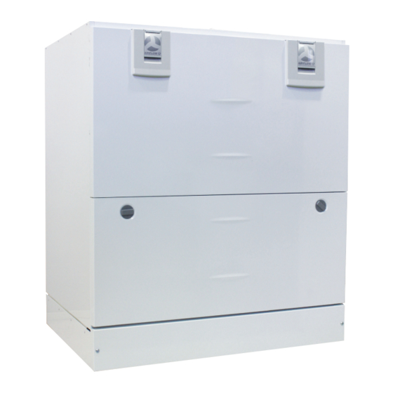
DV245 (Integral CO Sensor) INTRODUCTION MAIN PARTS OF THE VENTILATION UNIT R model in the figure Supply air fan Extract air fan Internal humidity sensor (behind the electric box) Fine filter for supply air Internal carbon dioxide sensor (behind the electric box) Heat recovery cell, 2 pcs Control panel Bypass damper of the HR cell... -
Page 5: System Description
9. Click on the link given in this e-mail to verify your e-mail The lastest browser versions on address. mobile devices. 10. You are now connected to the Adroit Cloud. © Airflow • We reserve the right to make changes without prior notice... - Page 6 DV245 (Integral CO Sensor) INTRODUCTION GENERAL SAFETY INSTRUCTIONS For safe and proper handling, it is necessary to know the basic safety regulations and the intended usage of the ventilation system. Read this manual before operating the ventilation unit. Keep this manual for later use.
-
Page 7: Adroit Digital Controller
These icons indicate the hierarchy level of the settings. This icon indicates when the feature is turned off at your user level. The parental controls lock code is 1001. © Airflow • We reserve the right to make changes without prior notice... - Page 8 DV245 (Integral CO Sensor) INTRODUCTION INTRODUCTION WARNING Ventilation has to be constant for the indoor air to stay healthy for the dwellers and the structures of the dwelling. Even for longer The unit is not intended for use holidays, it is not advisable to stop the ventilation, because the by children under 8 or by persons indoor air will become stuffy and, during the heating season, the with reduced sensory, physical or...
- Page 9 When the update is ready, the unit will restart automatically is ready, the unit will restart automatically. © Airflow • We reserve the right to make changes without prior notice...
-
Page 10: Deployment Wizard
DV245 (Integral CO Sensor) BASIC SETTINGS DEPLOYMENT WIZARD Start the Adroit ventilation unit. Press the OK button. The deployment wizard is launched. SELECTING THE LANGUAGE Select the user interface language as follows: Use the arrow buttons to select the language. Select OK. -
Page 11: Expert Settings
The following chapters describe the ventilation device deployment wizard phase, where you activate the expert settings. IMPORTANT Some deployment phases require special equipment, such as an air flow meter. © Airflow • We reserve the right to make changes without prior notice... - Page 12 DV245 (Integral CO Sensor) EXPERT SETTINGS PASSWORD AND ACCESS LEVEL Once you have finished up the basic settings, the deployment wizard moves on to setting the system password. NOTE If you set the password as 0000, the password inquiry is not used. The deployment wizard Password and access level screen is opened.
- Page 13 If, at the beginning, the air flows differ greatly from the designed rate. Check the air flows by measuring them at the valves, and fine tune the airflow rates, if necessary by first adjusting the units fans, then by adjusting the room valves.
- Page 14 DV245 (Integral CO Sensor) EXPERT SETTINGS PROFILE SETTINGS In the following chapters, you can make ventilation settings for the system profiles. AT HOME PROFILE When you want to set the At home profile settings, proceed as follows: 1. The deployment wizard At home screen will open. NOTE When the units fans have been set (step 5 in the deployment wizard) these values will default to the At home profile fan speed...
- Page 15 VOC content, is used or not. 15. The automatic fan speed control, based on the carbon dioxide or VOC content, is now set. 16. Press the OK button. © Airflow • We reserve the right to make changes without prior notice...
- Page 16 DV245 (Integral CO Sensor) EXPERT SETTINGS BOOST PROFILE When you want to set the Boost profile settings, proceed as follows: 1. The deployment wizard Boost profile screen is opened. NOTE Once you have set the fan speed for the At home profile, the fan speed for the Boost profile will default to +30% of the At home profile fan speed.
- Page 17 (or the week clock) change the profile. 15. The profile timer function is now set. 16. Press the OK button. 17. The Fireplace function settings are now complete. © Airflow • We reserve the right to make changes without prior notice...
- Page 18 DV245 (Integral CO Sensor) EXPERT SETTINGS FINISHING UP When you have completed the wizard, the Setup done! screen will open. Finish up the deployment, as follows: If you want to go back to repair or change a value, use the arrow buttons to select the desired line and press the OK button.
-
Page 19: Using The Unit
- The carbon dioxide or VOC level is significantly higher than normal. • The fan speed will be automatically increased if automatic adjustment has been chosen. © Airflow • We reserve the right to make changes without prior notice... - Page 20 DV245 (Integral CO Sensor) VENTILATION PROFILES CHANGING THE PROFILE If you want to change the ventilation profile, proceed as follows: Press the Change profile button until the desired ventilation profile icon appears on the display. Wait until the main display of the ventilation profile appears. The ventilation profile will now be changed.
- Page 21 Change filters — Indicates the next recommended filter change date. • Days in use — Indicates how long the unit has been running in days and years.. © Airflow • We reserve the right to make changes without prior notice...
- Page 22 DV245 (Integral CO Sensor) VENTILATION PROFILES VIEWING THE BOOST PROFILE INFORMATION To view the Boost profile settings, proceed as follows: Open the Boost profile main view. Press the Profile information button. The first information screen for the profile is opened. This screen contains the following information: •...
- Page 23 14. Use the Plus and Minus buttons to select whether the automatic fan speed control, based on the carbon dioxide or VOC level, is used or not. 15. Press the OK button. © Airflow • We reserve the right to make changes without prior notice...
- Page 24 DV245 (Integral CO Sensor) VENTILATION PROFILES MODIFYING THE AWAY PROFILE SETTINGS Open the Away profile main view. Press the Profile information button. Press the Edit button. The fan speed setup opens. Set the Away profile fan speed as a percentage of the maximum by using the Plus and Minus buttons.
- Page 25 19. The profile timer duration setting screen is opened. 20. Set the profile timer duration by using the Plus and Minus buttons. 21. Press the OK button. © Airflow • We reserve the right to make changes without prior notice...
- Page 26 DV245 (Integral CO Sensor) VENTILATION PROFILES MODIFYING THE FIREPLACE PROFILE SETTINGS When you want to edit the Fireplace function settings, proceed as follows: Open the Fireplace function main view. Press the Profile information button. Press the Edit button. The fan speed setup screen is opened. Use the Plus and Minus buttons to set the Fireplace function duration in minutes.
-
Page 27: Temperatures And Sensors
14. You can return to daily statistics by pressing the Minus button. 15. You can return to the temperature type selection by pressing the Back button. 16. Press the Right arrow button. © Airflow • We reserve the right to make changes without prior notice... - Page 28 DV245 (Integral CO Sensor) TEMPERATURES AND SENSORS A graph is opened, describing the supply air temperature over the last 24 hours. If you want to view weekly statistics, press the Plus button. A graph is opened, describing the supply air temperature over the last seven days.
- Page 29 Carbon dioxide statistics for the past week. You can You can view the graph for a week or for a single day. view the graph for a week or for a single day. © Airflow • We reserve the right to make changes without prior notice...
- Page 30 DV245 (Integral CO Sensor) SETTINGS FILTER SETTINGS When you want to browse through the filter settings, proceed as follows: Select Settings > Filter. Press the OK button. The filter status summary screen is opened. This screen contains the following information: •...
- Page 31 The maintenance reminder reminds you of the filter replacement with a pop-up window. To acknowledge the maintenance reminder message, press the OK button. Press the clock button to postpone the reminder for one week. © Airflow • We reserve the right to make changes without prior notice...
- Page 32 DV245 (Integral CO Sensor) SETTINGS DISPLAY SETTINGS SETTING THE SLEEP TIME The control panel automatically switches to sleep mode when the pre-set sleep time has elapsed. To set the sleep time, proceed as follows: Select Settings > Display settings. Press the OK button. The Display settings 1/2 appears.
- Page 33 The Time and date settings open. Press the Right arrow until the display 3/4 opens. Press the Plus button. The Dayl.Saving Time setting value is changed to On. Press the OK button. © Airflow • We reserve the right to make changes without prior notice...
- Page 34 DV245 (Integral CO Sensor) SETTINGS TIME AND DATE SETTING THE DATE To set the date, proceed as follows: Select Settings > Time and date. Press the OK button. The Time and date settings are opened. Press the Right arrow until the display 4/4 appears. Use the Plus and Minus buttons to set the date.
- Page 35 Press the Select button. A confirmation screen is opened. The week clock is now disabled. If you have set a weekly program, it will be saved in the system. © Airflow • We reserve the right to make changes without prior notice...
- Page 36 DV245 (Integral CO Sensor) SETTINGS REMOVING THE WEEKLY PROGRAM If you want to remove the weekly program settings from the system, proceed as follows Select Settings > Week clock. Press the OK button. Press the Settings button. The Week clock menu opens. Select Remove all settings.
- Page 37 The ventilation unit has now been turned off To re-start the ventilation unit, press any key. We advise against switching off the unit as the chosen ventilation system is continuous. © Airflow • We reserve the right to make changes without prior notice...
-
Page 38: Maintenance
The filter change interval depends on the ambient dust concentration. It is recommended that the filters be changed every spring and autumn, or at the very least once a year. Using original Airflow filters ensures that the ventilation unit remains in top condition, giving the best results. - Page 39 11. The heat recovery cell has now been checked and cleaned. Handle the cells carefully! Do not lift the cells by the plates, as the cell plates are very fragile. © Airflow • We reserve the right to make changes without prior notice...
- Page 40 DV245 (Integral CO Sensor) MAINTENANCE FANS Check the cleanliness of the fans when servicing the filters and the heat recovery cell. Clean the fans as required. You can clean the fan blades with compressed air or by brushing them gently. NOTE Only the supply air fan is equipped with a sound-damping grid.
- Page 41 WARNING Connect the cables so that they do not touch the heater. WARNING Before removing the heater from the unit, make sure it is not hot. © Airflow • We reserve the right to make changes without prior notice...
-
Page 42: Heat Recovery Cell
DV245 (Integral CO Sensor) MAINTENANCE TROUBLESHOOTING NOTE Error messages are displayed on the control panel and in the Adroit Home and Adroit Cloud services. FAULT CAUSE MEASURES Message on the user interface: The extract air fan has stopped. Make sure that the fan is not running. The fan cabling Extract fan stopped and operation must be checked, and if necessary the fan must be replaced. -
Page 43: Installation
MEASURING TUBES The accessories delivered with the unit include four airflow measuring tubes. These can be inserted in the ducts to allow for easier ventilation adjustment. © Airflow • We reserve the right to make changes without prior notice... -
Page 44: Technical Specifications
(l/s) 1008 1080 Input power (total W) SFP = Airflow specified in the ventilation plan (extract l/s) Volume flow rate SOUND VALUES Sound power level in the supply air duct Sound power level in the extract air duct (one duct) by octave band L... - Page 45 Outdoor air to the unit Exhaust air flowing outdoors from the unit Extract air from the apartment to the unit Supply air from the unit to the apartment © Airflow • We reserve the right to make changes without prior notice...
-
Page 46: External Electrical Connection
DV245 (Integral CO Sensor) EXTERNAL ELECTRICAL CONNECTION CABLE COLOURS Black Blue 230 V 50 Hz Brown MB_A MB_A MB_B MB_B +24V +24V RS_A RS_A White RS_B RS_B MOTHERBOARD Grey TESTER Yellow +24V +24V RS_A RS_A RS_B YEGN Yellow-green RS_B +11V1 +24V AN/I D/I1... - Page 47 AN/I = Analog input 0-10VDC RS_A Local hardware Modbus A signal RM/I 24V relay input RS_B Local hardware Modbus B signal RM/O 24V relay output External temperature sensor connector © Airflow • We reserve the right to make changes without prior notice...
- Page 48 DV245 (Integral CO Sensor) EXTERNAL ELECTRICAL CONNECTION FOR CONTROLLING THE DUCT RADIATOR 24 VDC relay/ contactor for controlling the pump and solenoid valve Distribution board +24VDC Ethernet connection on top of the unit RJ45 Female control Mains supply cable VENTILATION UNIT INTERNAL ELECTRICAL CONNECTION +24V +24V direct current voltage (DC)
- Page 49 Heat collection circuit One-way valve. Not included in the delivery. The pressure loss must be less than the External NTC sensor pressure loss of the heat pump. © Airflow • We reserve the right to make changes without prior notice...
-
Page 50: Heating And Cooling Radiator Operation Charts
DV245 (Integral CO Sensor) HEATING AND COOLING RADIATOR OPERATION CHARTS OPERATION AND SAMPLE CONNECTION NOTE Always follow first and foremost the connection diagram provided by the HVAC designer or heat pump manufacturer. If the duct radiator is used The accompanying figure shows an example of the arrangement in the supply air duct, it can for connecting the heating/cooling radiator unit to the heat only be used for cooling. -
Page 51: Exploded View And Parts List
60000274 stand grid Extract air G4 filter stand 60000264 19 Safety switch 60000135 29 Adroit motherboard 60000581 Lower support for HR cell 60000265 20 Connection box 60000208 © Airflow • We reserve the right to make changes without prior notice... -
Page 52: Certificate Of Conformity
+ A1:2011 This is the original Declaration of Conformity Alan Siggins Date 14th May 2019 Managing Director airflow Developments limited Aidelle House, Lancaster Road, Cressex Business Park High Wycombe, Buckinghamshire. HP12 3QP, U.K. T: +44 (0)1494 425252 E: info@airflow.com W: airflow.com... -
Page 53: User Level Diagrams
External sensor settings Display settings Heating settings Panel address Professional settings Modbus settings Basic fan settings I/O and bus settings Lock code and access rights Defrost settings © Airflow • We reserve the right to make changes without prior notice... -
Page 54: Commissioning The System
• Has been installed in accordance with latest Building Regulations and IEEE wiring regulations by a recognised competent installer. Airflow Developments Ltd shall not be liable for any loss, injury or other consequential damage, in the event of a failure of the...
Need help?
Do you have a question about the Adroit DV245 and is the answer not in the manual?
Questions and answers