Table of Contents
Advertisement
Quick Links
Advertisement
Table of Contents

Subscribe to Our Youtube Channel
Related Manuals for Airflow RF MEV WH4H

Summary of Contents for Airflow RF MEV WH4H
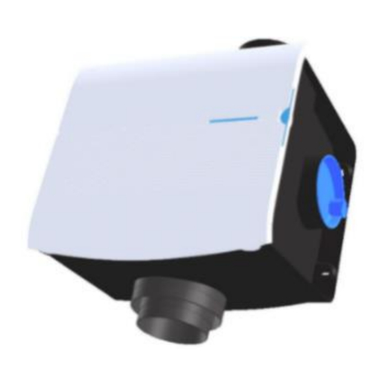
- Page 1 80001183 – Issue 2 10/22 Installation / Operation and Service Guide RF MEV WH4H Part No: 90001575 Mechanical Central Extract Ventilation Unit with Built in Humidity Sensor For unit versatility it is supplied without a controller. A choice of controllers is available.
-
Page 2: Table Of Contents
Contents Page Nº Heading Unit Dimensions Unit Specifications Transport and Storage Electrical Installation PCB Main Features Mechanical Installation Duct Connection Pairing Remote Controls Fan Performance Settings Flow Pressure Graphs Service and Maintenance Fan and Packaging Disposal Assorted Accessories Warranty Page 2 of 27... -
Page 3: Unit Dimensions
Unit Dimensions Air from rooms Air to outside Page 3 of 27... -
Page 4: Unit Specifications
Unit Specifications Voltage Required: 230V – 50Hz – 1Ph Two setting choices with three fan speed bands in each available: Low Bands = Two speeds in each – 70 to 138m³/h Watts= 3 to 5 Medium Bands = Eight speeds in one and four in the other –... -
Page 5: Transport And Storage
Any damage to the fan or packaging should be inspected by a suitably qualified person returned Airflow Developments Ltd for inspection before use. Fans should not be lifted or carried by an electrical lead, if fitted. Page 5 of 27... -
Page 6: Electrical Installation
Electrical Installation All electrical installations must be carried out by an approved electrician in accordance with the latest IET BS7671 Requirements for Electrical Installation, Low Voltage Directive 2014/35/EU, Machinery Directive 89/392/CE or the appropriate regulations in the country of installation. All fans require a 240V 50 Hz single phase supply. - Page 7 Immediately switch off the fan should any problems be found, and contact Airflow Developments Ltd. Fan motors used are suitable for continuous running and have a rated duty type S1 (motor is suitable to this duty type and rating at which the fan may be operated for an unlimited period).
-
Page 8: Pcb Main Features
PCB Main Features LED Red / Green Push button Picture of dipswitch Picture of dipswitch Mains power in 230V – 50 – 1Ph Cable to RF DIP Switches Receiver Page 8 of 27... -
Page 9: Mechanical Installation
If the Unit is found to be damaged, it should be returned to the supplier immediately. Units should be installed to a sufficiently solid structure giving adequate support. Fixings suitable for the mounting surface should be used. Airflow Developments Rubber mount... - Page 10 Mechanical Installation contd. Fan Tray Lifting Points Mounting Slots Page 10 of 27...
-
Page 11: Duct Connection
See page 3. If the ducting from this port is installed vertically a condensation trap should be fitted (Airflow part number: 90001242). 125mm diameter ridged ducting, or a ridged duct with at least 90% free surface area of 125mm diameter duct should be used. -
Page 12: Pairing Remote Controls
Duct Connection contd. Final connections can be made with a short length of flexible ducting (Airflow part number: 52641009) and the correct sealing clamps (Airflow part number: 51849403). The use of excessive amounts of flexible ducting will result in high system pressures and a noisy system. - Page 13 Paring Remote Controls Cont. When electric power to the unit is re-installed the LED red / green on the PCB (See page 8) will flash red and green then remain green for 3 x minutes. In this time the RF controllers can be paired to the unit. Basic Controller (90001489) Pariing Note: Ensure controller has a battery fitted.
- Page 14 Paring Remote Controls Cont. CAUTION!! Risk of Electric Shock. Do not touch other parts of the PCB as they remain live. After which the LED will remain green for 3 x minutes. In this time the controller can be paired to the unit by pressing the “1”...
- Page 15 PCB. (See page 8) for 15 x seconds until the LED is simultaneously red and green (orange). Release the push button, the LED will flash red–green–red. All connections to controllers are now cut. The airflow requirements of a dwelling should be Page 15 of 27...
-
Page 16: Fan Performance Settings
Fan Performance Settings calculated and conform to Building Regulations Part F,Volume1. This unit has two airflow performance curves to choose from. Each performance curve is broken down into three bands, low, medium, and high. Each band has a number of fan speeds to choose from. - Page 17 Fan Performance Settings Cont. Table A Page 17 of 27...
- Page 18 Fan Performance Settings Cont. Table B Page 18 of 27...
-
Page 19: Flow Pressure Graphs
Flow / Pressure Graph A Page 19 of 27... - Page 20 Flow / Pressure Graph B Page 20 of 27...
-
Page 21: Service And Maintenance
Failure to do so causes excess system pressure which will reduce the systems airflow, make the system noisier and ultimately lead to fan unit failure. To clean the unit, firstly remove the unit’s white, top protective cover held on by “D”... - Page 22 After re-connecting the electrical supply, the unit should be switched on. If there is any undue noise, switch the unit off immediately and the fault rectified. If the fault cannot be found contact Airflow Developments Ltd for advice at sales@airflow.com. Page 22 of 27...
-
Page 23: Fan And Packaging Disposal
Fan and Packaging Disposal These fan units consist mainly of steel, iron, aluminium, copper, electrical insulation materials, cables, wires, and plastic. Complete fans and parts that are at end of life due to wear and tear, corrosion, fatigue and or other effects that cannot be discerned must be disposed of in the correct manner conforming to local and / or international guidelines and regulations. -
Page 24: Assorted Accessories
Assorted Accessories Page 24 of 27... -
Page 25: Warranty
Warranty Airflow guarantees the Central Extract Fan Unit: MEV WH4H designated in these instructions for 2 years from date of purchase against faulty material or workmanship. Applicable to units installed and used in the UNITED KINGDOM. Warranty covers the fan and not the reinstallation if required. - Page 26 Airflow Developments Ltd shall not be liable for any loss, injury, or other consequential damage, in the event of a failure of the equipment, arising from, or in connection with, the equipment excepting only that nothing in this condition shall be construed as to exclude or restrict liability for negligence.
- Page 27 Unit Service Notes Page 27 of 27...
Need help?
Do you have a question about the RF MEV WH4H and is the answer not in the manual?
Questions and answers