Table of Contents
Advertisement
Quick Links
Advertisement
Table of Contents

Related Manuals for Evikon PluraSens E2638-HFC


Summary of Contents for Evikon PluraSens E2638-HFC
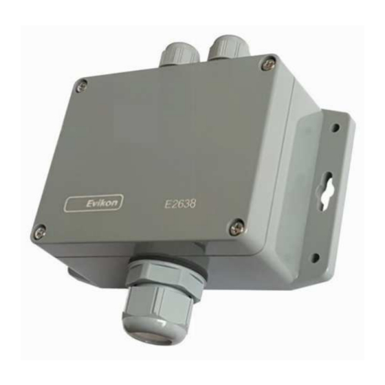
- Page 1 ® PluraSens Refrigerant Detector-Transmitter E2638-HFC User Manual...
-
Page 2: Table Of Contents
E2638-HFC Rev 21.06.2021 Table of contents Hydrofluorocarbons Specifications Product description Safety requirements Operating conditions Installation guidelines Mounting dimensions Sensor probe handling Gas sensor replacement procedures Electrical connections Correct and incorrect cabling for 24 VAC Operation Maintenance Calibration Delivery set Order code for E2638-HFC options Configuring Return to default settings Modbus RTU Communication... -
Page 3: Hydrofluorocarbons
E2638-HFC Rev 21.06.2021 Hydrofluorocarbons HFCs are relatively non-flammable, chemically stable, and nonreactive. Classification of halocarbon refrigerants Group Refrigerants Chlorofluorocarbons (CFC) R11, R12 Hydrochlorofluorocarbons R22, R141b, R142b (HCFC) Hydrofluorocarbons (HFC) R32, R125, R134a, R143a Hydrofluoroolefins (HFO) R 1234ez, R1234yf, R1336mzz Chlorine-containing refrigerants (CFC and HCFC) are considered to be damaging to the ozone layer and contributing to the greenhouse effect. - Page 4 E2638-HFC Rev 21.06.2021 asphyxiation in confined spaces. At higher temperatures (>250°C) decomposition products may include hydrofluoric acid (HF) and carbonyl halides. An escape of refrigerant through a leak may damage the refrigerating facilities.
-
Page 5: Specifications
E2638-HFC Rev 21.06.2021 Specifications Sampling method Diffusion Standard: Metal oxide semiconductor Sensor type NDIR sensor available on demand Typical detection range 0...1000 ppm Resolution / digital unit 1 ppm Response time T90 <120 s Sensor lifetime (MOS) > 5 years Calibration interval 12 months Signal update... - Page 6 E2638-HFC Rev 21.06.2021 Relay option 2 × SPST relays (closing contact), Output relays 250 VAC / 30 VDC, 5 A max RE1 (LOW): set 100 ppm; release 80 ppm Default alarm setpoints RE2 (HIGH): set 500 ppm; release 400 ppm Signalling options Visual Red and green LEDs...
-
Page 7: Product Description
E2638-HFC Rev 21.06.2021 Product description E2638 series detectors-transmitters belong to the PluraSens® family of multifunctional measurement instruments. The instruments utilize gas sensors of various types with excellent repeatability, stability, and long lifetime. E2638 series provides two independent analog outputs OUT1 and OUT2, user-selectable to 4-20 mA or 0-10 V, proportional to gas concentrations. -
Page 8: Operating Conditions
E2638-HFC Rev 21.06.2021 Operating conditions The device should be used both in a non-hazardous area and in a basic electromagnetic environment, where the latter is defined in EN 61326-1. Avoid strong mechanical shock and vibrations. Avoid corrosive atmosphere and areas highly contaminated with dust, oil mist, etc. -
Page 9: Mounting Dimensions
E2638-HFC Rev 21.06.2021 Mounting dimensions Front view Bottom view... -
Page 10: Sensor Probe Handling
E2638-HFC Rev 21.06.2021 Sensor probe handling The E2638 series devices are available with a remote probe. The remote probe is connected to the main unit with a shielded cable. The default remote probe cable length is 3 m. Wall mount remote probe with fixing clamp (default version), Remote probe with rubber flange and three self-tapping screws (on request) The sensor probes of all types are equipped with a hydrophobic microporous PTFE filter to protect the sensor from dust, dirt, and water drops. -
Page 11: Electrical Connections
E2638-HFC Rev 21.06.2021 Electrical connections Unscrew four lid screws and detach the lid from the device. Use two M16 cable glands to let in the cables of the power supply and of the external devices. Without turning on the power, plug the power cable, and connect the analog/relay outputs and/or digital interface terminals to the necessary devices according to the relevant connection diagram. - Page 12 E2638-HFC Rev 21.06.2021 Jumpers OUT1 type (open: 4-20 mA; closed 0-10 V) OUT2 type (open: 4-20 mA; closed 0-10 V) Reset Modbus network parameters to default X4 terminals OUT1 4-20 mA / 0-10 V output OUT2 4-20 mA / 0-10 V output 0 V / 24 VAC Neutral (optional) RS485 A / Data + RS485 B / Data -...
-
Page 13: Correct And Incorrect Cabling For 24 Vac
E2638-HFC Rev 21.06.2021 NOTE! The outputs are not galvanically isolated from the external power supply and share a common 0V. Allowed load resistance limits are stated in the Specifications table. To power the instrument from an external power source, connect terminals 0V and +U to the source. If the integrated mains power supply module is used, connect terminals L and N to the mains. -
Page 14: Operation
E2638-HFC Rev 21.06.2021 Operation Turn on the power. The instrument warm-up time takes about 1 minute after switching on and the final sensor stabilization time to maximum accuracy takes <60 minutes. The operating status is indicated by the LED on the PCB of the device. The control LED (red) response to different processes is presented in the following table: Mode LED mode... -
Page 15: Delivery Set
E2638-HFC Rev 21.06.2021 Delivery set Detector-transmitter E2638 ● Mounting accessories: ● 4 screws with plastic dowels ○ Fixing clamp for remote probe version ○ Order code for E2638-HFC options E2638 options Order code Remote probe, 3 m cable E2638-HFC-RP33-3 Remote probe, 10 m cable E2638-HFC-RP33-10 Duct mount option, stem Ø35×L230 mm E2638-HFC-DM... -
Page 16: Configuring
E2638-HFC Rev 21.06.2021 Configuring A standard configuration kit includes a USB-RS485 converter, fixed flow regulator, gas tubing with applicators, and a software pack. Please contact your Seller for more information. Detectors-transmitters E2638 share all functionalities of the PluraSens® multifunctional platform. The features and options include: ●... -
Page 17: Modbus Rtu Communication
E2638-HFC Rev 21.06.2021 Modbus RTU Communication RS485 communication interface Databits: 8 Supported Modbus functions: Parity: none / odd / even 03 – Read multiple registers Stop bits: 1 or 2 06 – Write a single register Protocol: Modbus RTU Communication parameters Parameter Permitted values Default... - Page 18 E2638-HFC Rev 21.06.2021 1200, 2400, 4800, 9600, 19200, 0x0005 5 / 40006 RW Baud rate * 9600 38400, 57600 0x0006 6 / 40007 RW Response delay, ms 1...255 1 – No parity bit, 1 stop bit (default after factory reset) 2 –...
- Page 19 E2638-HFC Rev 21.06.2021 0 –none 2 – gas concentration 211 / Parameter tied to relay 0x00D3 9 – control by Modbus 40212 control, state set in MHR / 40214 0 – none 2 – gas concentration 212 / Parameter tied to relay 0x00D4 9- –...
- Page 20 E2638-HFC Rev 21.06.2021 0 – none 220 / 0x00DC RW Control logic for relay RE2 1 – relay on at high values 40221 2 – relay on at low values 3 – relay on at values within the range 4 – relay on for the values out of the range 221 / LOW setpoint for relay...
- Page 21 E2638-HFC Rev 21.06.2021 bit[8]=0/1 – LED deactivated/activated bit[9]=0/1 – buzzer deactivated/activated bit[10]=0/1 - LED is on/off in normal condition bit[11]=0/1 - 1 Hz (50% on, 50% off) LED signal off/on if relay1 turned on bit[12]=0/1 - 2 Hz (50% on, 50% off) LED signal off/on if relay2 turned on 257 /...
-
Page 22: Warranty
Manufacturer or damaged by customer error or negligence or if there has been an unauthorized modification. Manufacturer contacts Evikon MCI OÜ Teaduspargi 7/9, Tartu 50411 Estonia info@evikon.eu...
Need help?
Do you have a question about the PluraSens E2638-HFC and is the answer not in the manual?
Questions and answers