
Subscribe to Our Youtube Channel
Related Manuals for Cincoze P1100 Series

Summary of Contents for Cincoze P1100 Series
- Page 1 P1100 Series User Manual Display Computing Solution Slim Embedded Computer with CDS Technology Version: V1.22...
-
Page 2: Table Of Contents
3.1 Removing the Top Cover ……...……………………………….….…………………..30 3.2 Installing SO-DIMM Memory………………………..…………..…………….……………31 3.3 Installing Mini-PCIe Cards on Bottom Side……..……………………………..32 3.4 Installing Antennas…….…….…………..……….…………………………………………..33 3.5 Installing CPU Thermal Pad.……………………………………………………..………..35 3.6 Assembling the System….…..…...……….………...….……………………………....36 3.7 Installing a SATA Hard Drive…………………………………………………………………37 P1100 Series | User Manual... - Page 3 4.7 Save & Exit …...……….….………………….…..….…..………………………....64 Chapter 5 Product Application (For CMI-DIO100 Only) 5.1 Digital I/O (DIO) application ………..………………………………………………………66 5.1.1 Digital I/O Programming Guide ……………………………………………………66 5.2 Digital I/O (DIO) Hardware Specification ……………………………………………………72 5.2.1 DIO Connector Definition ………………..……...…………….........72 P1100 Series | User Manual...
- Page 4 Chapter 6 Optional Modules and Accessories 6.1 Location of the Connectors for CMI Modules……………………...………………………75 6.2 Installing a CFM-IGN Module...…….………………………………………………….……..75 6.3 Installing a CFM-PoE Module…….…..……………………………….……..……….……..83 P1100 Series | User Manual...
-
Page 5: Revision
2020/10/22 Copyright Notice © 2018 by Cincoze Co., Ltd. All rights are reserved. No parts of this manual may be copied, modified, or reproduced in any form or by any means for commercial use without the prior written permission of Cincoze Co., Ltd. All information and specification provided in this manual are for reference only and remain subject to change without prior notice. -
Page 6: Product Warranty Statement
Product Warranty Statement Warranty Cincoze products are warranted by Cincoze Co., Ltd. to be free from defect in materials and workmanship for 2 years from the date of purchase by the original purchaser. During the warranty period, we shall, at our option, either repair or replace any product that proves to be defective under normal operation. -
Page 7: Technical Support And Assistance
Limitation of Liability Cincoze’ liability arising out of the manufacture, sale, or supplying of the product and its use, whether based on warranty, contract, negligence, product liability, or otherwise, shall not exceed the original selling price of the product. The remedies provided herein are the customer’s sole and exclusive remedies. -
Page 8: Conventions Used In This Manual
11. If the equipment is not used for a long time, disconnect it from the power source to avoid damage by transient overvoltage. 12. Never pour any liquid into an opening. This may cause fire or electrical shock. P1100 Series | User Manual... - Page 9 The equipment has obvious signs of breakage. ⚫ 14. CAUTION: Danger of explosion if battery is incorrectly replaced. Replace only with the same or equivalent type recommended by the manufacturer. 15. Equipment intended only for use in a RESTRICTED ACCESS AREA. P1100 Series | User Manual...
-
Page 10: Package Contents
Note: Notify your sales representative if any of the above items are missing or damaged. Ordering Information Model No. Product Description Intel® Atom® E3950 Quad Core Slim Embedded Computer with P1101-E50-R10 CDS Technology Intel® Pentium® N4200 Quad Core Slim Embedded Computer with P1101-E42-R10 CDS Technology P1100 Series | User Manual... -
Page 11: Optional Modules & Accessories
18AWG/3C Black 1.8M SL-2+SL-3 EU 2 heads power cord, EU G type to IEC C13, H05VV-F SL6-SL3 0.75mm2/3G Black 1.8M SL-6+SL-3 UK 2 heads power cord, UK I type to IEC C13, H05VV-F QP026-SL3 0.75mm2/3G Black 1.8M QP026+SL-3 P1100 Series | User Manual... -
Page 12: Chapter 1 Product Introductions
Chapter 1 Product Introductions P1100 Series | User Manual... -
Page 13: Overview
(CDS/VGA/DisplayPort) and enables smooth 4K2K (@60Hz) playback via DisplayPort. P1100 Series offers extensive connectivity including 2x GbE, 4x USB 3.0, 4x COM, 4x DI/4x DO, 2x full-size Mini-PCIe slot and 1x SIM socket. For storage requirements, the system provides 1x 2.5"... -
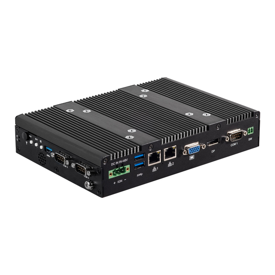
Page 14: Product Pictures
2x Full Size Mini-PCIe Expansion Socket ⚫ Supports 2x PoE+ Function (with optional CFM module) ⚫ Supports Ignition Sensing Function (IGN) (with optional CFM module) ⚫ Supports CDS Technology for Convertible Panel PC ⚫ Built-in Two 2W Internal Speakers P1100 Series | User Manual... -
Page 15: Hardware Specification
• Surge Protection: 3.84 kV (impedance 12 ohm 1.2/50μs - Function waveform) • Supports Convertible Display System (CDS) Technology Operating System - CDS Interface for Convertible Display Module • 4x Antenna Holes • Windows® 10 • Linux: Supports by project P1100 Series | User Manual... -
Page 16: System I/O
COM 1 supports RS232/422/485 serial LAN port device Used to connect the system to a local area Remote Power On/Off Terminal Block network Used to plug a remote power on/off terminal block Used to connect an analog VGA monitor P1100 Series | User Manual... - Page 17 Used to connect a speaker The Digital I/O terminal block supports 4 Antenna Hole digital input and 4 digital output Used to install an antenna jack USB 3.0 port Used to connect USB 3.0/2.0/1.1 device P1100 Series | User Manual...
-
Page 18: Mechanical Dimension
1.6.5 Top VESA Mounting Hole These are mounting holes for VESA mount (75x75mm and 100x100mm) 1.7 Mechanical Dimension P1100 Series | User Manual... - Page 19 Chapter 2 Switches & Connectors P1100 Series | User Manual...
-
Page 20: Location Of Switches And Connectors
2.1 Location of Switches and Connectors 2.1.1 Top View P1100 Series | User Manual... -
Page 21: Bottom View
2.1.2 Bottom View P1100 Series | User Manual... -
Page 22: Switches And Connectors Definition
Mini PCI-Express / mSATA Socket Power1 / Power2 +5V / +12V Power Output POE_PH2 POE Board to Board Connector IGN_PH3 IGN Board to Board Connector PWR_SW1 Power Switch LVDS_OUT1 LVDS Connector SATA1 SATA with Power Connector P1100 Series | User Manual... -
Page 23: Definition Of Switches
BL_PWR1: Backlight Power on / off Switch Definition Push Backlight Power on / off switching BL_UP1: Backlight Increase Switch Definition Push Backlight Increase BL_UP2: Backlight Decrease Switch Definition Push Backlight Decrease RESET1: Reset Button Switch Definition Push Reset System P1100 Series | User Manual... - Page 24 0V (RI) ON (Default) ON (Default) COM1 Location Function DIP3 DIP4 0V (RI) ON (Default) ON (Default) COM2 LED1: Power / HDD Access LED Status LED Color Status POWER ON POWER Green HDD Read/Write Blinking Yellow P1100 Series | User Manual...
-
Page 25: Definition Of Connectors
12 SIM_CLK SMB_CLK 48 +1.5V PETN0 (USB3TN0) / 13 REFCLK+ 49 NA SATATN0 14 SIM_Reset SMB_DATA 50 GND PETP0 (USB3TP0) / 15 GND 51 NA SATATP0 16 SIM_VPP 52 +3.3V 17 NA 18 GND USB_D- P1100 Series | User Manual... - Page 26 47 NA 12 NA SMB_CLK 48 +1.5V 13 REFCLK+ PETN0 / ATATN0 49 NA 14 NA SMB_DATA 50 GND 15 GND PETP0 / SATATP0 51 NA 16 NA 52 +3.3V 17 NA 18 GND USB_D- P1100 Series | User Manual...
- Page 27 Ignition (IGN) LAN1 / LAN2: LAN LED Status Definition Act LED Status Definition Blinking Yellow Data Activity No Activity Link LED Status Definition Steady Green 1Gbps Network Link Steady Orange 100Mbps Network Link 10Mbps Network Link P1100 Series | User Manual...
- Page 28 Connector Type: 9-pin D-Sub RS422 / 485 RS485 RS232 Full Duplex Half Duplex Definition Definition Definition DATA - DATA + POWER1/ POWER2: Power Connector Connector Type: 1x4 4-pin Wafer, 2.0mm pitch Pin 1 Definition +12V P1100 Series | User Manual...
-
Page 29: Chapter 3 System Setup
Chapter 3 System Setup P1100 Series | User Manual... -
Page 30: Removing The Top Cover
3.1 Removing the Top Cover 1. Loosen the 8 screws of front and rear panel, then place them aside. 2. Remove the cover from the chassis. Place the top cover gently. P1100 Series | User Manual... -
Page 31: Installing So-Dimm Memory
2. Tilt the SO-DIMM module at a 45-degree angle and insert it to SO-DIMM socket until the gold-pated connector of module contacted firmly with the socket. 45° 3. Press the modules down until it’s fixed firmly by the two locking latches on each side. P1100 Series | User Manual... -
Page 32: Installing Mini-Pcie Cards On Bottom Side
Insert the Mini-PCIe card at a 45-degree angle and insert it to the slot until the gold-pated connector of module contacted firmly with the slot. 45° Press down the module and fasten two screws to secure the module. P1100 Series | User Manual... -
Page 33: Installing Antennas
If you have a Half-size Mini-PCIe card, make sure use extender to make it Full-size as shown below. 3.4 Installing Antennas 1. Remove the antenna hole covers at front panel. 2. Have antenna jack penetrate through the hole. P1100 Series | User Manual... - Page 34 3. Put on washer and fasten the nut with antenna jack. 4. Assemble the antenna and antenna jack together. 5. Attach the RF connector at another end of cable onto the module. P1100 Series | User Manual...
-
Page 35: Installing Cpu Thermal Pad
3.5 Installing CPU Thermal Pad 1. Place the thermal pad on the CPU heatsink. P1100 Series | User Manual... -
Page 36: Assembling The System
3.6 Assembling the System 1. Put on the cover. 2. Fasten the 8 screws to fix the cover. P1100 Series | User Manual... -
Page 37: Installing A Sata Hard Drive
3.7 Installing a SATA Hard Drive 1. Loosen 2 screws on front panel to remove cover plate. 2. Turn over the unit to have the bottom side face up and loosen 1 screw. 3. Pull out the HDD bracket. P1100 Series | User Manual... - Page 38 4 provided screws to assemble HDD and HDD bracket together. 5. Align the HDD bracket with the entrance of HDD bay. And insert the HDD bracket until the connector of HDD contact the SATA connector firmly. P1100 Series | User Manual...
-
Page 39: Installing A Sim Card
3.8 Installing a SIM Card 1. Loosen 2 screws on front panel to remove cover plate. 2. SIM card slot is at the front panel of the system. 3. Insert the SIM card. P1100 Series | User Manual... -
Page 40: Connecting With Cv / Cs Display Module
2. Turn over the unit to have the bottom side face up, loosen the 2 screws of the module connector bracket. The photos show the male connector (on display module) and female connector (on PC module) P1100 Series | User Manual... - Page 41 3. Connect the module. 4. Fasten the 6 screws to fix the PC module on the display module. P1100 Series | User Manual...
-
Page 42: Wall Mount Brackets
De-attach six rubber holes from the mounting brackets as indicated. 2. Assemble two wall mount brackets by fastening three screws at each side. The following picture indicates four wall mounting holes at each side. P1100 Series | User Manual... - Page 43 3. Attach the P1100 series to wall by fastening six screws through mounting holes at each side as illustrated. P1100 Series | User Manual...
-
Page 44: Din-Rail Mount Bracket
3.11 DIN-Rail Mount Bracket P1100 series offers DIN-Rail Mount that customer can install system on the DIN Rail 1. Assemble two wall mount brackets by fastening three screws at each side. P1100 Series | User Manual... - Page 45 2. The mounting holes are at the two wall mount brackets. Fasten the 4 screws to fix the DIN-Rail mount bracket with system together. P1100 Series | User Manual...
-
Page 46: Vesa Mount Bracket
3.12 VESA Mount Bracket The following picture indicates VESA mounting hole pattern on P1100 series, which is compliant with VESA mounting standard. 1. Please fasten eight screws as indicated to fix it on the stand. VESA stand P1100 Series | User Manual... -
Page 47: Chapter 4 Bios Setup
Chapter 4 BIOS Setup P1100 Series | User Manual... -
Page 48: Bios Introduction
You can use arrow keys ( ↑↓ ) to highlight the field and press <Enter> to call up the sub-menu. Then you can use the control keys to enter values and move from field to field within a sub-menu. If you want to return to the main menu, just press the <Esc >. P1100 Series | User Manual... -
Page 49: Main Setup
Use arrow keys to move among the items and press <Enter> to accept or enter a sub-menu. 4.2.1 System Date Set the date. Please use <Tab> to switch between date elements. 4.2.2 System Time Set the time. Please use <Tab> to switch between time elements. P1100 Series | User Manual... -
Page 50: Advanced Setup
■ Enable ACPI Auto Configuration [Disabled] Enables or disables BIOS Advanced Configuration Power Interface® (ACPI) auto configuration. ■ Enable Hibernation [Enabled] Enables or disables system ability to hibernate state (OS/S4 state). This option may not be effective with some OS. P1100 Series | User Manual... -
Page 51: F81866 Super Io Configuration
Enables or disables Lock Legacy Resources. 4.3.2 F81866 Super IO Configuration Set Parameters of Serial Ports. User can Enable/Disable the serial port and Select an optimal setting for the Super IO Device. ■ Serial Port 1~4 Configuration. P1100 Series | User Manual... -
Page 52: Hardware Monitor
■ Watch Dog Timer [0] Allows you to set watchdog timer’s value in the range of 0 to 255. 4.3.3 Hardware Monitor This screen displays the current status of all monitored hardware devices/components such as voltages, temperatures. P1100 Series | User Manual... -
Page 53: S5 Rtc Wake Settings
[Dynamic Time]: Sets an increase minute(s) from current time to wake system from S5. 4.3.5 Serial Port Console Redirection ■ Console Redirection [Disabled] Allow users to enable or disable COM1, COM2, COM3, COM4 console redirection function. P1100 Series | User Manual... -
Page 54: Cpu Configuration
Enables or disables Intel Virtualization Technology. Virtualization enhanced by Intel Virtualization Technology will allow a platform to run multiple operating systems and applications in independent partitions. With virtualization, one computer system can function as multiple virtual systems. 4.3.7 Network Stack Configuration P1100 Series | User Manual... -
Page 55: Csm Configuration
[UEFI]: Enables UEFI option ROM only. [Legacy]: Enables legacy option ROM only. ■ Video [UEFI] Controls the execution of UEFI and Legacy Video option ROM. [Do not launch]: Disables option ROM execution. [UEFI]: Enables UEFI option ROM only. P1100 Series | User Manual... -
Page 56: Usb Configuration
Enables or disables XHCI (USB3.0) hand-off function. Use this feature as a workaround for operating systems without XHCI hand-off support. ■ USB Mass Storage Driver Support [Enabled] Enables or disables USB mass storage driver support. P1100 Series | User Manual... -
Page 57: Chipset Setup
4.4 Chipset Setup This section allows you to configure chipset related settings according to user’s preference. 4.4.1 North Bridge This section provides information on the installed memory size and memory/onboard graphics-related configuration options. P1100 Series | User Manual... -
Page 58: South Bridge
■ Amplifier Function [Enabled] Enables or disables Amplifier Function. ■ PSE Enable Selection [Enabled] Enables or disables PSE (Power Sourcing Equipment). ■ LAN1 [Enabled] Enables or disables LAN1 Controller. ■ LAN2 [Enabled] Enables or disables LAN2 Controller. P1100 Series | User Manual... -
Page 59: South Cluster Configuration
❑ PCIe Speed [Auto] Allows you to select PCI Express port speed. Configuration options: [Auto] [Gen1] [Gen2]. PCI Express Root Port 6 (MiniPcie) ❑ PCI Express Root Port 6 (MiniPcie) [Enabled] Enables or disables PCI Express Root Port. P1100 Series | User Manual... - Page 60 Configuration options: [Auto] [Gen1] [Gen2]. ■ SATA Devices SATA Port 0 ❑ Port 0 [Enabled] Enables or disables SATA Port 0. SATA Port 1 Port 1 [Enabled] ❑ Enables or disables SATA Port 1. ■ Miscellaneous Configuration P1100 Series | User Manual...
- Page 61 ❑ Wake On Lan [Enabled] Enables or disables Wake On LAN (WOL) function. ❑ BIOS Lock [Disabled] Enables or disables BIOS the SC BIOS Lock enable feature. It is required to be enabled to ensure SMM protection of flash. P1100 Series | User Manual...
-
Page 62: Security Setup
This section allows users to configure BIOS security settings. 4.5.1 Administrator Password Administrator Password controls access to the BIOS Setup utility. 4.5.2 User Password User Password controls access to the system at boot and to the BIOS Setup utility. P1100 Series | User Manual... -
Page 63: Boot Setup
Allows you to enable or disable Fast Boot function. If enabled, system boots with initialization of a minimal set of devices required to launch active boot option. ■ Hard Drive BBS Priority Allows you to set the order of the legacy devices in this group. P1100 Series | User Manual... -
Page 64: Save & Exit
■ Save as User Defaults This item allows you to save the changes done so far as user defaults. ■ Restore User Defaults This item allows you to restore the user defaults to all the setup options. P1100 Series | User Manual... -
Page 65: Chapter 5 Product Application (For Cmi-Dio100 Only)
Chapter 5 Product Application P1100 Series | User Manual... -
Page 66: Digital I/O (Dio) Application
This section describes DIO application of the product. The content and application development are better understood and implemented by well experienced professionals or developers. 5.1.1 Digital I/O Programming Guide 5.1.1.1 Pins for Digital I/O of Cincoze P1001 series product Item Standard GPIO74 (Pin107) - Page 67 5.1.1.3 Relative Registers To program the F81866A configuration registers, see the following configuration procedures. P1100 Series | User Manual...
- Page 68 // Set (bit 4~7) = 0 to select GP 74~77 as Input mode. <Input Value> WriteByte(AddrPort, 0x82) // Select configuration register 82h ReadByte(DataPort, Value) // Read bit 4~7 (0xFF)= GP74 ~77 as High. <Leave the Extended Function Mode> WriteByte(AddrPort, 0xAA) P1100 Series | User Manual...
- Page 69 // Set (bit 0~3) = 1 to select GP 80 ~83 as Output mode. <Output Value> WriteByte(AddrPort, 0x89) // Select configuration register 89h WriteByte(DataPort, Value) // Set bit 0~3=(0/1) to output GP 80~83 as Low or High <Leave the Extended Function Mode> WriteByte(AddrPort, 0xAA) P1100 Series | User Manual...
- Page 70 5.1.1.5 Change base address - DIO base address (Cincoze default 0xA00) <Enter the Extended Function Mode> WriteByte(AddrPort, 0x87) WriteByte(AddrPort, 0x87) // Must write twice to enter Extended mode <Select Logic Device> WriteByte(AddrPort, 0x07) WriteByte(dataPort, 0x06) // Select logic device 06h...
- Page 71 7 6 5 4 3 2 1 0 = DI4 = DO4 1 0 0 0 - - - - value - - - - 1 0 0 0 value 5.1.1.7 DIO I/O Port Address P1100 Series | User Manual...
-
Page 72: Digital I/O (Dio) Hardware Specification
Signal High Level: Pull up resistor to XCOM+ Signal Low Level: = XCOM- Sink Current: 1A (Max) 5.2.1 DIO Connector Definition DIO1: Digital Input / Output Connector Connector Type: Terminal Block 1X10 10-pin, 3.5mm pitch Definition Definition XCOM+ (DC INPUT) XCOM- (GND) P1100 Series | User Manual... - Page 73 P1100 Series | User Manual...
- Page 74 Chapter 6 Optional Modules and Accessories Pin Definitions and Settings P1100 Series | User Manual...
- Page 75 6.2 Installing a CFM-IGN Module 1. Locate the IGN connector on system motherboard as indicated. 2. Insert CFM-IGN module vertically to the female connector on the system’s mainboard, and fasten 2 screws to fix it. P1100 Series | User Manual...
- Page 76 Pin 4 Definition 0 second 1 minute 5 minutes 10 minutes 30 minutes 1 hour 2 hours Reserved (0 second) 24V_12V_1: 12V / 24V Car Battery Switch Definition 24V Car Battery Input 12V Car Battery Input P1100 Series | User Manual...
- Page 77 1. Locate the PoE connector on system motherboard as indicated. 2. Insert the female connector of CFM-PoE module to the male connector on system motherboard. 3. Turn over the heatsink and paste the thermal pad onto the marked by red squares. P1100 Series | User Manual...
- Page 78 4. Paste the heatsink onto the CFM-PoE module carefully and fasten 2 screws to fix it. 5. Paste the thermal pads onto the heatsink and coil carefully. 6. When the system is power on, please note that the POE LED will light on if the POE module is properly installed. P1100 Series | User Manual...
- Page 79 © 2020 Cincoze Co., Ltd. All rights reserved. The Cincoze logo is a registered trademark of Cincoze Co., Ltd. All other logos appearing in this catalog are the intellectual property of the respective company, product, or organization associated with the logo.
Need help?
Do you have a question about the P1100 Series and is the answer not in the manual?
Questions and answers