Sign In
Upload
Download
Table of Contents
Contents
Add to my manuals
Delete from my manuals
Share
URL of this page:
HTML Link:
Bookmark this page
Add
Manual will be automatically added to "My Manuals"
Print this page
×
Bookmark added
×
Added to my manuals
Manuals
Brands
Masport Manuals
Water Pump
HXL5W
Owner's/operator's manual
Masport HXL5W Owner's/Operator's Manual
Hide thumbs
Also See for HXL5W
:
Owner's/operator's manual
(44 pages)
1
2
3
4
5
6
Table Of Contents
7
8
9
10
11
12
13
14
15
16
17
18
19
20
21
22
23
24
25
26
27
28
29
30
31
32
33
34
35
36
37
38
39
40
41
42
43
44
45
46
47
48
page
of
48
Go
/
48
Contents
Table of Contents
Troubleshooting
Bookmarks
Table of Contents
Table of Contents
Introduction
Intended Use
Installation
Plumbing
Recommended System Components
Component Checklist
Drive Systems
Rotation of the Pump
Pump Speeds and Power Requirements
Fan Cooled Models
Liquid Cooled Models
Vacuum Relief Valve
Pressure Relief Valve
Pump Lubrication
Flushing Information
Maintenance and Important Operating Tips
Troubleshooting
Pump Service
Exploded Views
Advertisement
Quick Links
1
Introduction
2
Pump Speeds and Power Requirements
3
Pump Lubrication
4
Flushing Information
5
Maintenance and Important Operating Tips
6
Troubleshooting
7
Pump Service
8
Exploded Views
Download this manual
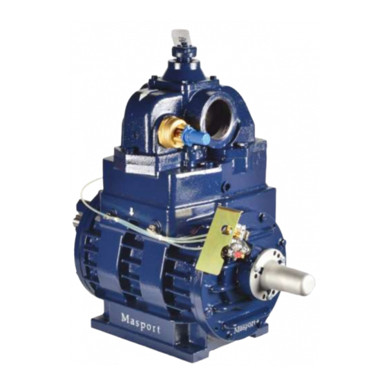
Owner/Operator Manual
For Pump Models: HXL5W, HXL75, HXL75W,
HXL15, HXL15W, VIPER and HXL400W
Warning! This Manual includes important product safety information. Misuse of this
product may result in severe injury or death. Read this manual carefully before attempting
to use this product.
Table of
Contents
Previous
Page
Next
Page
1
2
3
4
5
Advertisement
Table of Contents
Need help?
Do you have a question about the HXL5W and is the answer not in the manual?
Ask a question
Questions and answers
Related Manuals for Masport HXL5W
Water Pump Masport H Series Owner's/Operator's Manual
(44 pages)
Water Pump Masport H Series Owner's/Operator's Manual
(44 pages)
Water Pump Masport H Seeries Manual
Vacuum pressure pumps (62 pages)
Water Pump Masport HXL400W Owner's/Operator's Manual
(48 pages)
Water Pump Masport HXL75 Owner's/Operator's Manual
(48 pages)
Water Pump Masport HXL75V Owner's/Operator's Manual
Vacuum/pressure pump (26 pages)
Water Pump Masport HXL400WV Owner's/Operator's Manual
Vacuum/pressure pump (26 pages)
Water Pump Masport HYDRA Owner's/Operator's Manual
(53 pages)
Water Pump Masport VIPER Owner's/Operator's Manual
(48 pages)
Water Pump Masport TITAN Owner's/Operator's Manual
(53 pages)
This manual is also suitable for:
Hxl75
Hxl75w
Hxl15
Hxl15w
Viper
Hxl400w
Table of Contents
Print
Rename the bookmark
Delete bookmark?
Delete from my manuals?
Login
Sign In
OR
Sign in with Facebook
Sign in with Google
Upload manual
Upload from disk
Upload from URL


Need help?
Do you have a question about the HXL5W and is the answer not in the manual?
Questions and answers