
Related Manuals for Stulz CyberCool 2


Summary of Contents for Stulz CyberCool 2
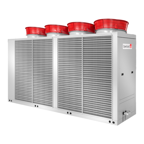
- Page 1 CyberCool 2 Original instructions Precision Chillers Scroll compressor Index G42 400V/50Hz/3Ph/N/PE Issue 6.2018...
- Page 2 CY B E R CO O L 2 S C R O L L O R I G I N A L I N S T R U C T I O N S A B O U T S T U L Z Since it was founded in 1947, the STULZ company has evolved into one of the world’s leading system suppliers of air-conditioning technology.
- Page 3 The high-end chiller Dear customer, we are pleased that you have decided for a CyberCool 2 Chiller from STULZ. The units, which were produced in Hamburg, have been developed especially for use in Data Cen- ters and industry and satisfy all requirements for efficiency and reliability.
- Page 4 CY B E R CO O L 2 S C R O L L O R I G I N A L I N S T R U C T I O N S EN/06.2018/G42 © STULZ GmbH – all rights reserved...
-
Page 5: Table Of Contents
10. Contents of the CE Declaration of Conformity ..........77 11. Options ......................78 11.1 Option anti vibration mount ................... 78 11.2 Option AxiTop........................80 11.3 Option lateral power supply ..................82 11.4 Option anti-corrosion coating ..................84 Subject to technical modifications. © STULZ GmbH – all rights reserved EN/06.2018/G42... -
Page 6: Safety
• Refrigerants have a narcotic effect when inhaled in high concentrations. • I f unavoidable work is required in the presence of a high concentration of refrigerant, breathing apparatus must be worn. This does not mean simple filter masks. Comply with breathing protection data sheet. • Do not eat, drink or smoke at work. • Warning against intentional misuse. • It is absolutely essential to comply with the first aid measures if accidents occur. • R efrigerants containing FCs contribute to the global warming and with this to climate changes. The EN/06.2018/G42 © STULZ GmbH – all rights reserved... -
Page 7: Duties Of The Operator
The operator is responsible for the execution. The operator must ensure that all maintenance, inspection and assembly work is carried out by authorised and qualified specialist staff who have made an in-depth study of the operating instructions. independent conversion and manufacture of replacement parts The system may only be converted or modified after consultation with STULZ. Original replacement parts and replacement parts/accessories authorised by STULZ are an aid to safety. © STULZ GmbH – all rights reserved EN/06.2018/G42... -
Page 8: Transport / Storage
• You receive the consignment papers with the delivery of the chiller unit. • The shipment is made ex works, in case of shipment damages, please assert your claim towards the carrier. 2.2 Storage If you put the unit into intermediate storage before the installation, the following measures have to be carried out to protect the unit from damage and corrosion: • t he storage point must not be exposed to direct sunlight. Observe the storage conditions in the chapter “Application limits“. • store the unit packaged to avoid the risk of corrosion. • m ake sure that the water connections are provided with protective hoods. EN/06.2018/G42 © STULZ GmbH – all rights reserved... -
Page 9: Transport
1400 The drawings on the following pages show the dimensions for the sus- pension points and the position of the centre of gravity. max 100 Clamps to lock min 150 the rope or belt © STULZ GmbH – all rights reserved EN/06.2018/G42... - Page 10 801 aSn cSo 541 aSF 1057 cSo 621 aSF 1068 cSo 801 aSF 1012 1090 cQo 541 aSn cQo 621 aSn cQo 541 aSF 1068 cQo 621 aSF 1079 The co-ordinates of the centre of gravity are indicated with a tolerance of ± 50 mm. EN/06.2018/G42 © STULZ GmbH – all rights reserved...
- Page 11 D must have the same length. cSo 1102 aSF 1785 1830 cSo 1302 aSF 1820 1882 cQo 802 aSn 1650 1442 cQo 1102 aSn 1702 1565 cQo 802 aSF 1730 1722 cQo 1102 aSF 1785 1849 The co-ordinates of the centre of gravity are indicated with a tolerance of ± 50 mm. © STULZ GmbH – all rights reserved EN/06.2018/G42...
- Page 12 • After installation, remove the lifting lugs and keep them for future transport. notice • consider also the weight of the cross beams when you order the crane. • T he rope forces are higher than the weight forces according to the geometry. • Due to the risk of scratching the side planking, we advise, not to use chains. EN/06.2018/G42 © STULZ GmbH – all rights reserved...
- Page 13 1850 3615 cQo 1302 aSn 1680 2808 cQo 1602 aSn 1710 3112 cQo 1902 aSn 1720 3154 cQo 1302 aSF 1920 3247 cQo 1602 aSF 1860 3555 cQo 1902 aSF 1860 3597 The co-ordinates of the centre of gravity are indicated with a tolerance of ± 50 mm. © STULZ GmbH – all rights reserved EN/06.2018/G42...
- Page 14 4626 cQo 2402 aSn 2180 3713 cQo 2802 aSn 2200 3779 cQo 3702 aSn 1880 4319 cQo 2402 aSF 2290 4295 cQo 2802 aSF 2300 4366 cQo 3702 aSF 2000 4907 The co-ordinates of the centre of gravity are indicated with a tolerance of ± 50 mm. EN/06.2018/G42 © STULZ GmbH – all rights reserved...
- Page 15 3600 5300 G: unit transport weight Modell Model S [mm] g [kg] S: centre of gravity cSo 4202 aSn 2410 4540 The ropes or belts named by A, B, C and cSo 4202 aSF 2660 5374 D must have the same length. The co-ordinates of the centre of gravity are indicated with a tolerance of ± 50 mm. © STULZ GmbH – all rights reserved EN/06.2018/G42...
- Page 16 6738 cQo 4002 aSn 2790 5035 cQo 4602 aSn 2630 5558 cQo 5002 aSn 2830 5234 cQo 4002 aSF 3095 6017 cQo 4602 aSF 2950 6542 cQo 5002 aSF 3130 6207 The co-ordinates of the centre of gravity are indicated with a tolerance of ± 50 mm. EN/06.2018/G42 © STULZ GmbH – all rights reserved...
- Page 17 At the delivery the chiller is equipped with flexible plates made of polypropylene, which are fixed at the condenser coils. If the unit is equipped with the option "coil protection grille" the protection grilles must be unscrewed to remove the polypropylene plates. • Remove these plates before start-up. Coil protection grille (optional) + housing protection grille (optional) option: coil protection grille The spacers are enclosed in the electrical cabinet. • Unscrew the coil protection grille (6 screws). • Remove the transport protection plates. • P lace the spacers (4 pieces each) on the protection grille. • Fix the coil protection grille. Spacer 6 x screw M6 4 x spacer © STULZ GmbH – all rights reserved EN/06.2018/G42...
-
Page 18: Description
Number of refrigerant circuits: 1, 2 - No. Nominal cooling capacity [kW] Installation: O - outside Sound version: S - standard Q - Quiet, low-noise Chiller type: C - scroll compressor, DX EN/06.2018/G42 © STULZ GmbH – all rights reserved... -
Page 19: Intended Use
This chiller unit is used for the chilled water production and for the chilled water temperature control. The chill- er is designed for outdoor installation. Any use beyond this is not deemed to be use as intended. STULZ is not liable for any damage resulting from such misuse. - Page 20 An electronic expansion valve is also part of the standard equipment as a filter dryer with replaceable car- tridge and a sight glass with humidity indication. Each refrigerant circuit disposes of the following safety devices: - low pressure switch - high pressure limiter with reset button - safety valve EN/06.2018/G42 © STULZ GmbH – all rights reserved...
- Page 21 A thermostatically controlled air/water heat exchanger for cooling at high ambient temperatures is situated inside the electric cabinet on the left side. Fan, aspirating warm air out of the electric cabinet © STULZ GmbH – all rights reserved EN/06.2018/G42...
- Page 22 Auslösung bei releases at automatischer Reset bei automatic reset at Hochdruckbegrenzer High pressure limiter Auslösung bei releases at Manueller Reset möglich bei manual reset possible at Sicherheitsventil Safety valve Auslösung bei releases at EN/06.2018/G42 © STULZ GmbH – all rights reserved...
-
Page 23: Technical Data
C...O 3702 - C...O 5902 17,5 °C CQO 802 15 °C at maximum compressor capacity, water volume flow according to design conditions 18/12°C and outdoor temperature 35°C. The temperatures may vary during the start phase. © STULZ GmbH – all rights reserved EN/06.2018/G42... - Page 24 (a) full load at 18°C/12°C water temperature inlet/outlet (b) full load at 18°C/14°C water temperature inlet/outlet (min. dTw), outdoor temperature 35°C (c) full load at 18°C/10°C water temperature inlet/outlet (max. dTw), outdoor temperature 35°C EN/06.2018/G42 © STULZ GmbH – all rights reserved...
- Page 25 >1 Sulphide mg/l <1 Nitrate mg/l <100 Nitrite mg/l <0,1 Iron mg/l <0,2 Manganese mg/l <0,1 Free aggressive carbonic acid mg/l <20 Suspended solids mg/l <30 Electric conductivity µS/cm 10 ... 500 © STULZ GmbH – all rights reserved EN/06.2018/G42...
-
Page 26: Technical Data
(3): Sound power level (full load) under free field conditions (according to ISO 3744) (4): Water inlet temperature 18°C, glycol content 30%, outdoor temperature 6°C Transport weight = net weight + weight of refrigerant charge Operating weight = transport weight + weight of water content EN/06.2018/G42 © STULZ GmbH – all rights reserved... - Page 27 Länge Length 2300 4200 3950 Breite Width 1300 1300 2300 Höhe Height 2350 2350 2510 Baugröße Construction size Transportgewicht Transport weight 1550 1602 3081 3123 Betriebsgewicht Operating weight 1023 1589 1655 3137 3196 © STULZ GmbH – all rights reserved EN/06.2018/G42...
- Page 28 Höhe Height 2510 2510 2510 2510 Baugröße Construction size 6½ Transportgewicht Transport weight 3177 3741 4276 4044 4540 5503 5182 5765 Betriebsgewicht Operating weight 3256 3866 4442 4221 4731 5760 5443 6047 EN/06.2018/G42 © STULZ GmbH – all rights reserved...
- Page 29 Breite Width 1300 1300 2300 Höhe Height 2350 2350 2510 Baugröße Construction size Transportgewicht Transport weight 1057 1068 1090 1830 1882 3520 3562 Betriebsgewicht Operating weight 1124 1136 1165 1972 2037 3689 3748 © STULZ GmbH – all rights reserved EN/06.2018/G42...
- Page 30 Höhe Height 2510 2510 2510 2510 Baugröße Construction size 6½ Transportgewicht Transport weight 3615 4323 4858 4626 5374 6477 6145 6738 Betriebsgewicht Operating weight 3808 4611 5187 4966 5784 7009 6682 7296 EN/06.2018/G42 © STULZ GmbH – all rights reserved...
- Page 31 Länge Length 2300 4200 3950 Breite Width 1300 1300 2300 Höhe Height 2350 2350 2510 Baugröße Construction size Transportgewicht Transport weight 1442 1565 2808 3112 Betriebsgewicht Operating weight 1004 1474 1605 2862 3169 © STULZ GmbH – all rights reserved EN/06.2018/G42...
- Page 32 Width 2300 2300 2300 Höhe Height 2510 2510 2510 Baugröße Construction size Transportgewicht Transport weight 3154 3713 3779 4319 5035 5558 5234 Betriebsgewicht Operating weight 3228 3792 3904 4486 5212 5817 5498 EN/06.2018/G42 © STULZ GmbH – all rights reserved...
- Page 33 4200 3950 Breite Width 1300 1300 2300 Höhe Height 2350 2350 2510 Baugröße Construction size Transportgewicht Transport weight 1068 1079 1722 1849 3247 3555 Betriebsgewicht Operating weight 1135 1147 1874 1991 3411 3726 © STULZ GmbH – all rights reserved EN/06.2018/G42...
- Page 34 Width 2300 2300 2300 Höhe Height 2510 2510 2510 Baugröße Construction size Transportgewicht Transport weight 3597 4295 4366 4907 6017 6542 6207 Betriebsgewicht Operating weight 3785 4575 4657 5239 6543 7079 6749 EN/06.2018/G42 © STULZ GmbH – all rights reserved...
-
Page 35: Dimensional Drawings
2 s c r o l l o r i g i n a l i n s T r U c T i o n s 4.3 Dimensional drawings Construction size 3 1300 2300 Construction size 4 1300 4200 Construction size 5 2300 3950 © STULZ GmbH – all rights reserved EN/06.2018/G42... - Page 36 2 s c r o l l o r i g i n a l i n s T r U c T i o n s Construction size 6 2300 5030 Construction size 6½ 2300 6170 Construction size 7 7250 2300 EN/06.2018/G42 © STULZ GmbH – all rights reserved...
-
Page 37: Installation
NOtICE Screwed pipe joints can loosen by long transportation distances. • Before final commissioning, check all screwed pipe joints in the refrigerant circuit and chilled water circuit on tightness. © STULZ GmbH – all rights reserved EN/06.2018/G42... - Page 38 Keep a clearance of 1 m around the unit to every side. • Above the fans a clearance of 2,5 m is required. Maintenance clearance Space needed for individual installation and multiple unit installation EN/06.2018/G42 © STULZ GmbH – all rights reserved...
-
Page 39: Weights On The Supports
CSO 801 ASN CSO 541 ASF CSO 621 ASF CSO 801 ASF CQO 541 ASN CQO 621 ASN CQO 541 ASF CQO 621 ASF The weights are indicated with a tolerance of ±5%. © STULZ GmbH – all rights reserved EN/06.2018/G42... - Page 40 CSO 1102 ASN CSO 1302 ASN CSO 1102 ASF CSO 1302 ASF CQO 802 ASN CQO 1102 ASN CQO 802 ASF CQO 1102 ASF The weights are indicated with a tolerance of ±5%. EN/06.2018/G42 © STULZ GmbH – all rights reserved...
- Page 41 CQO 1602 ASF The weight on the support Mxr (M1, M2, M3, M4) CQO 1902 ASF is equal to the weight on the support Mxl. The weights are indicated with a tolerance of ±5%. © STULZ GmbH – all rights reserved EN/06.2018/G42...
- Page 42 CQO 2802 ASF The weight on the support Mxr (M1, M2, M3, M4) CQO 3702 ASF is equal to the weight on the support Mxl. The weights are indicated with a tolerance of ±5%. EN/06.2018/G42 © STULZ GmbH – all rights reserved...
- Page 43 CSO 4202 ASN CSO 4202 ASF The weights are indicated with a tolerance of ±5%. The weight on the support Mxr (M1, M2, M3 ... M5) is equal to the weight on the support Mxl. © STULZ GmbH – all rights reserved EN/06.2018/G42...
- Page 44 CQO 5002 ASF The weights are indicated with a tolerance of ±5%. The weight on the support Mxr (M1, M2, M3 ... M5) is equal to the weight on the support Mxl. EN/06.2018/G42 © STULZ GmbH – all rights reserved...
-
Page 45: External Water Circuit
If you connect two or more chillers in parallel, we recommend to install regulating valves to keep the pressure drop of each unit equally high. return water flow water Chiller 1 Chiller 2 © STULZ GmbH – all rights reserved EN/06.2018/G42... - Page 46 An access is possible via the rear side of the chiller. in the direction of the arrow. • Move both free cooling valves manually before starting the chiller. During operation, a forced movement of the free cooling valve is configured by default. EN/06.2018/G42 © STULZ GmbH – all rights reserved...
- Page 47 Construction size 3: Size 3 + 4: Rear view Water inlet 120 ± 10 Water outlet Construction size 4: 120 ± 10 Construction size G1 1/2" G2 1/2" Chilled water connection internal thread internal thread © STULZ GmbH – all rights reserved EN/06.2018/G42...
- Page 48 Chilled water connection internal thread flange flange flange Construction size type CQO 2402 CQO 2802 CQO 3702 G2 1/2" G2 1/2" DN 80 DN 80 Chilled water connection internal thread int. thread flange flange EN/06.2018/G42 © STULZ GmbH – all rights reserved...
- Page 49 Chilled water connection flange Water outlet To avoid misunderstanding: The designation "water inlet" and "water outlet" are chosen, seen from the chiller. At the water outlet, the chilled water is provided from the chiller. © STULZ GmbH – all rights reserved EN/06.2018/G42...
- Page 50 • Remove the protective hoods from the water pipes. • Connect the external piping to the chilled water lines of the chiller free of mechanical stress. EN/06.2018/G42 © STULZ GmbH – all rights reserved...
-
Page 51: Electrical Connection
• establish an effective earthing to the unit frame. ESD NOtE Do not touch electronical components, without taking care of protective ESD measures. Electronical components: - C7000 IO controller (1) © STULZ GmbH – all rights reserved EN/06.2018/G42... - Page 52 (part of the unit documents). • secure these cables by the pull relief screw. EN/06.2018/G42 © STULZ GmbH – all rights reserved...
- Page 53 Control line Reserve Option: second power supply Power supply Air inlet Size 4: Condensate drain of Grounding el. cabinet cooling Control line Outside temp. sensor Reserve Option: second power supply Power supply Air inlet © STULZ GmbH – all rights reserved EN/06.2018/G42...
- Page 54 Connection of control lines (optional) If the chiller shall be connected to other Stulz units by the IO bus, to a BMS or contains opional extensions, you must route control lines and connect them in the electric cabinet of the chiller.
- Page 55 • Design the wiring between the controller and the contactor with reference to the connection diagram for the controller and the wiring between the pump and power switch according to the manufacturer's notes. © STULZ GmbH – all rights reserved EN/06.2018/G42...
-
Page 56: Commissioning
Lethal dose: 0,4 g ethylene glycol/kg body weight, severe intoxication: already at 0,1 ml/kg. Glycol is absorbed through the skin. Therefore immediately change clothing soaked with glycol. Wear protective gloves made of rubber. EN/06.2018/G42 © STULZ GmbH – all rights reserved... - Page 57 Deventilation valves Rubber plug to cover the vent valve openings Rubber plugs and blee- ding line in a chiller with free cooling (on this illustration the condenser fans are not yet installed.) © STULZ GmbH – all rights reserved EN/06.2018/G42...
-
Page 58: Control Of The Electrical Box
• Switch on the chiller unit at the master switch. The crankcase heater and the controller are now supplied with power, so you can use it for adjustments. EN/06.2018/G42 © STULZ GmbH – all rights reserved... - Page 59 Control circuit fuses Condenser fan Condenser fan power switch cir- power switch cir- cuit 2 cuit 1 Compressor Compressor power switch power switch circuit 2 circuit 1 Main switch Neutral terminal PE rail Power supply © STULZ GmbH – all rights reserved EN/06.2018/G42...
- Page 60 Electrical cabinet control section, right side User interface with display Service-Port X15 for connection of a PC/lap- top for operation IO controller board Driver module for electro- nic expansion valve plus battery module EN/06.2018/G42 © STULZ GmbH – all rights reserved...
- Page 61 • Press the "P" key. The set value and "SP" will be displayed alternately. • Adjust new setpoint by the keys. • Press "P" key to return to the display of the actual value. The hysteresis is fixed to 5 Kelvin. © STULZ GmbH – all rights reserved EN/06.2018/G42...
-
Page 62: Oil Pre-Heating
• In the meantime the laptop can be switched off and the connection to the I/O controller can be separated. • Keep the pump running for 8 hours and clean the implemented filter (recommended part of the external cir- cuit) after this lapse of time. EN/06.2018/G42 © STULZ GmbH – all rights reserved... -
Page 63: Commissioning Of The Refrigerant Circuits
The oil level should be between the lower quarter and the upper quarter of the sight glass. © STULZ GmbH – all rights reserved EN/06.2018/G42... - Page 64 • Perform the same checks as for the first refrigerant circuit. For all units • Switch off the manual mode for all components. handoff • Instruct the operational staff of the controller manipulation (refer to the C7000 controller manual). EN/06.2018/G42 © STULZ GmbH – all rights reserved...
-
Page 65: Maintenance
Water circuit Tightness Evaporator Unit housing Electrical box Unit interior ** depending on environment, in the proximity of trees and in case of low positioning of the chiller, a half-yearly control is required. © STULZ GmbH – all rights reserved EN/06.2018/G42... -
Page 66: Refrigerant Circuit
A pollution of the filter drier, whose essential task is to clear the refrigerant from impurities and humidity, can be detected by a temperature difference upstream and downstream the filter drier. • Compare the colour indicator in the centre of the sight glass with the outer ring scale. EN/06.2018/G42 © STULZ GmbH – all rights reserved... -
Page 67: Sight Glass
HP switch (high pressure limiter) When the HP limiter triggers, the compressor is switched off without delay. Before the restart and after the elimination of the error, the HP switch must be reset by pressing the red reset button. A check of the tripping function of the high pressure limiter (e.g. by cutting down the condenser fan and forc- ing a high pressure) is not possible without difficulties, as there are, on behalf of the C7000 controller, further monitoring functions via the high pressure sensor, which intervene in the compressor control (high pressure management). LP switch Check the correct function of the low pressure switch by stepwise closing the expansion valve of one refriger- ant circuit using the manual mode of the C7000 controller, while the compressor is running. Check by means of a pressure gauge connected at the low pressure side in the compressor section, whether the low pressure switch trips at 3 bar. When the LP switch trips, the compressor is switched off without delay. After the compressor pause (default setting: 180 sec.) has elapsed the compressor is restarted. During the evaluation delay (default setting: 120 sec., possibly raise on 300 sec.) you can stepwise open the expansion valve in manual mode, until you reach a suction pressure of 6 bar (check by suction pressure gauge). © STULZ GmbH – all rights reserved EN/06.2018/G42... -
Page 68: Compressor
The interaction between ester oil and water results in the formation of acid. Owing to a hyperacidity, corrosive processes take place inside the compressor. • In this case exchange the ester oil. Oil level During unit idleness the oil level should not be below the lower quarter (bottom line) and not rise above the upper line during operation. Oil type: ICI Emkarate RL 32-3MAF (factory filling) ICI Emkarate RL 32 CF • C heck the oil level by looking at the sight glass in the oil compensation line (for size 3/4 directly on the compressor). Crankcase heater Check the crankcase heater function by measuring the ohmic resistance at the terminals of the auxiliary con- tactor in the electric cabinet. For the 140W heater the ohmic resistance should approximately be 1,1 kOhm, 1,3 kOhm for the 120W heater and 1,8 kOhm for the 90W heater. EN/06.2018/G42 © STULZ GmbH – all rights reserved... -
Page 69: Air Circuit
The detergent "Snowclean marine SP" is highly concentrated and must be diluted with water. This detergent is aggressive towards painted, varnished and anodized aluminium surfaces! For coated finned heat exchangers and microchannel coils, we recommend a cleaning with just warm water without using chemicals. The detergent "Snowclean marine SP" would damage the coating. Procedure • first clean the coil with a vacuum cleaner and soft nozzle. • rinse from the inside out and from bottom to top. • direct the jet of water always vertically on the fins, to not distort the fins. • allow the detergent to react on the debris about 1-5 minutes, but do not let it dry. For rinsing, we recommend to use a high pressure washer with hot water of 50-80 °C. Rinsing with cold water is less effective. • rinse all wetted surfaces thoroughly. • rinse the debris from the inside out and from bottom to top, until the exiting water is completely clean. • d rain the water which has accumulated between the coils (sizes 5-7) by removing the plugs at the bottom plate. We accept no liability for consequential damages and improper application. © STULZ GmbH – all rights reserved EN/06.2018/G42... - Page 70 The electronics housing can get hot. The fans have an operation delay after the unit is stopped ! You need an appropriate secured access (e.g. working platform) to the chiller top, to dismount a condenser fan for each heat exchanger element. • open the centrally located cable duct on top of the chiller. The duct is divided into a part for the power lines and a narrower part for control lines. The fan is connected by a screwed plug connection in the power line part and two screwed plug connections in the control line part. • disconnect the electrical connections and protect them against damage and humidity. • completely unscrew the 4 Torx screws of the fan grille • lift the fan (weight: approx. 30 kg) with another person and place it upside down on a fan next to it. EN/06.2018/G42 © STULZ GmbH – all rights reserved...
-
Page 71: Water Circuit
Another possibility to verify this consists in the comparison of the chilled water outlet temperature with the saturated evaporation temperature (by measuring the suction pressure at the low pressure side of the com- pressor). If this difference exceeds 7 K, the evaporator is probably polluted. In this case the evaporator has to be cleaned chemically. Frost protection sensor Flow sensor Water outlet temperature sensor Water inlet temperature sensor Chilled water sensors Pump (option) The pump is equipped with permanently lubricated bearings. According to the manufacturer's instructions, the bearings have an expected durability of 20,000 operating hours. • check the pump for audible and visible wearing. • replace the bearings with noticeable wearing. • f or instructions on how to replace the bearing see QR-code on the pump or instruction sheet in the e Stulz area. © STULZ GmbH – all rights reserved EN/06.2018/G42... -
Page 72: Unit Housing
At the fan contactor, dangerous voltages occur. Do not open the unit within the first 5 minutes after disconnection of all phases. Due to the EC fans dangerous charges of >50µC can occur for a short time between AC line terminals and PE after disconnection. Electrical box • c heck the connection terminals for tight fixation when the unit is installed and once again after an operation time of 30 days. CAUTiOn The power contactors of the compressors must be checked on smooth operation and worn contacts every 10 years. Unit interior Clean pipes simplify the search for leaks. Vibrations of pipes and circuit components can result in leaks. • check the pipes for a tight seat. Condensing air humidity on cold water pipes means a loss of cooling capacity. • check the insulation of the water piping. EN/06.2018/G42 © STULZ GmbH – all rights reserved... -
Page 73: Malfunction
EEV #: Temperature The control module has detect- 1. Cable breakage or faulty contact Check cable and contacts. sensor error ed a malfunction of the temper- ature sensor. 2. Temperature sensor defective. Replace temperature sensor. # stands for a number in case of several components of the same kind. © STULZ GmbH – all rights reserved EN/06.2018/G42... - Page 74 No voltage is present at the 1. An external device has triggered Depending on the type of message. failure digital input for the external a signal. alarm #. 2. Cable breakage or faulty contact. Check wiring. # stands for a number in case of several components of the same kind. EN/06.2018/G42 © STULZ GmbH – all rights reserved...
- Page 75 1 0 0 0 In this case the circuit breaker has also triggered Alarm availability...:1 1 1 0 0 and cut off three fans, which are therefore no longer reachable via Modbus. The fans with the addr. 101, 102,103 can not be reached. © STULZ GmbH – all rights reserved EN/06.2018/G42...
-
Page 76: Dismantling And Disposal
• d isconnect the unit from the external water circuit by closing the external shut-off valves and drain the water circuit of the unit. • disconnect the depressurized chilled water pipes of the unit from the external system. • m ove the unit, as described in the chapter „transport“, with a lifting device of sufficient load-carrying capacity. • dispose of the chiller in accordance with the disposal and safety regulations applicable on site. We recommend a recycling company for this. The unit basically contains the raw materials aluminium (heat exchanger coils), copper (pipelines, wiring), iron (panelling, frames) and P235 steel (water piping). The electrical and electronical components installed in the electric cabinet must be separately disposed of according to the European directive 2012/19/EU. The concerned components are marked by the symbol of the crossed-out wheeled bin. EN/06.2018/G42 © STULZ GmbH – all rights reserved... -
Page 77: Contents Of The Ce Declaration Of Conformity
Name of notified body for inspection and monitoring Germanischer Lloyd SE of the Production Quality Assurance: Brooktorkai 18 D-20457 Hamburg national regulation Harmonised En EC-directives BGR 500 chapter 2.35 EN 378 -1, -2, -3, -4 EC machinery directive 2006/42/EC BGV A3 EN ISO 12100 EC directive for low voltage 2014/35/EU EN ISO 13857 EC EMC directive 2014/30/EU EN 60204 -1 RoHS directive 2011/65/EU EN 61000-6-2 EC pressure equipment directive 2014/68/EU EN 61000-6-4 2018 Year of manufacture: © STULZ GmbH – all rights reserved EN/06.2018/G42... -
Page 78: Options
The anti-vibration mounts protrude the lateral dimensions of the chiller by 59 mm. Base plate of anti-vibration mount Number of anti-vibration mounts per unit size Baugröße Size 6½ Anzahl Number 12,5 Size 3 - 4: Size 4 Size 3 EN/06.2018/G42 © STULZ GmbH – all rights reserved... - Page 79 • Keep in mind that the anti-vibration mounts under load yield up to 4 mm in height. • Now position the chiller on the provided support frame and fasten the anti-vibration mounts on this frame. washer washer © STULZ GmbH – all rights reserved EN/06.2018/G42...
-
Page 80: Option Axitop
The eight screws may be tightened with a torque of 9 Nm ± 1,4 Nm. external diffusor internal diffusor support ring cable cut-outs connection cables EN/06.2018/G42 © STULZ GmbH – all rights reserved... - Page 81 If the fan is entirely exchanged (not only the motor) it is appropriate to reuse the support ring at which the cooling tube is attached. 18 ± 3 mm cooling tube (for unit sizes 5-7) plastic clip © STULZ GmbH – all rights reserved EN/06.2018/G42...
-
Page 82: Option Lateral Power Supply
With this option you can feed in the power supply cables from the right or left side. Size 3 Feed in from left Feed in from right max. 3 holes Size 4 max. 3 holes EN/06.2018/G42 © STULZ GmbH – all rights reserved... - Page 83 2 s c r o l l o r i g i n a l i n s T r U c T i o n s Size 5 - 7 Feed in from right max. 3 x Ø65 Feed in from left max. 3 x Ø65 © STULZ GmbH – all rights reserved EN/06.2018/G42...
-
Page 84: Option Anti-Corrosion Coating
When using the anti-corrosion coating the cooling capacity specified in the technical data is reduced by 5-10%. The airside pressure loss increases by 0 - 5%. EN/06.2018/G42 © STULZ GmbH – all rights reserved... - Page 86 2 o r i g i n a l i n S T r U c T i o n S STULZ Top Service – more than just quick emergency assistance Technical manage-...
Need help?
Do you have a question about the CyberCool 2 and is the answer not in the manual?
Questions and answers