
Related Manuals for Stulz WSA Explorer Series


Summary of Contents for Stulz WSA Explorer Series
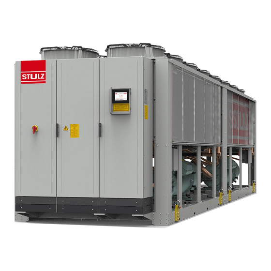
- Page 1 WSA Explorer Original instructions Water cooled liquid chillers Index i09 400V / ~3 / 50Hz Issue 06.2016...
- Page 2 - take advantage of our know-how. Founded in Hamburg in 1947, today STULZ has a presence in over 140 countries. The STULZ Group has STULZ subsidiaries in 17 countries, 7 production...
- Page 3 It is the result of many years of research and design studies, as well as a fine matching of materials and technologies to obtain a high quality chiller. The CE mark guarantees that the STULZ products fulfill the requirements of the European Machinery Directive for safety.
-
Page 4: Table Of Contents
5.1.2 Operating conditions ............................... 35 5.2 Chilled water quality .........................37 5.2.1 Glycol correction factors ............................37 5.3 Pressure Drops ............................38 5.4 Head pressure available .......................39 5.5 Technical Data .............................41 5.6 Dimensional drawings ........................52 EN/06.2016/i09 © STULZ S.p.A. – all rights reserved... - Page 5 8.5.3 Differential pressure switch ..........................80 8.6 Electric circuit ............................80 8.6.1 Powerboard ................................... 80 8.7 Unit in general ............................80 Malfunction ..................82 Dismantling and disposal ..............84 cE declaration of conformity ...............85 Options ....................86 Subjet to change without notice © STULZ S.p.A. – all rights reserved EN/06.2016/i09...
-
Page 6: Introduction
The initial startup of the chiller has to be carried out by trained personnel authorized from STULZ. Only STULZ approved spare parts and liquids are allowed to be used. All scheduled maintenance operations described in this manual must be performed accordingly by trained and qualified personnel. -
Page 7: Safety
Location: in the proximity of the input / output pipes of condensers (under the protective casing) and on the compressors. With equipped antifreeze option, even in the proximity of the heaters around the evaporator and the steel hydraulic piping. © STULZ S.p.A. – all rights reserved EN/06.2016/i09... - Page 8 HFC fluids causing greenhouse effect regulated by Kyoto protocol - Das Gerät erhält wie vom Kyoto-Protokoll geregelte Fluorkohlenwasserstoffe Treibhausgasen - Dispositif contenant fluides HFC à effet de serre disciplinés par le protocole de Kyoto MADE IN ITALY EN/06.2016/i09 © STULZ S.p.A. – all rights reserved...
-
Page 9: Safety Instructions
This cooling unit contains fluorinated greenhouse gas covered by the Kyoto protocol In these STULZ chillers the refrigerant R134a is used. Refrigerants are volatile or highly volatile fluorinated hydrocarbons which are liquefied under pressure. They are incombustible and not hazardous to health when used as intended. -
Page 10: Safety And Environmental Requirement
• Splashes of fluorinated hydrocarbons in the eyes can be blown out or fanned out by an assis- tant. Then rinse with water. independent conversion and manufacture of replacement parts The system may only be converted or modified after consultation with STULZ. Original replace- EN/06.2016/i09 © STULZ S.p.A. – all rights reserved... - Page 11 W SA Ex p lO r E r O r i g i n A l i n St r u c t i O n S ment parts and replacement parts/accessories authorised by STULZ are an aid to safety.
-
Page 12: Residual Risk
Wear safety gloves. Cover lower arms ture up to 70°C skin with clothing Electrical alimentation Falsely dimensioned cables or Short-circuit, fire, acid vapours Correctly design alimentation cables and protection devices protection elements. Wear protective mask EN/06.2016/i09 © STULZ S.p.A. – all rights reserved... -
Page 13: Maintenance
/ preparation Recommended uses Refrigerant 2. Composition/ Tetrafluoroethane CAS No. 811-97-2 (C2H2F4) CE No.: 212-377-0 Information on ingredients Concentration: 100% WArning please, refer to the specific “Safety Data Sheet” of refrigerant gas © STULZ S.p.A. – all rights reserved EN/06.2016/i09... - Page 14 Health studies have shown that chemical exposure may cause potential human health risks which may vary from person to person. WArning please, refer to the specific “Safety Data Sheet” of lubrificant oil EN/06.2016/i09 © STULZ S.p.A. – all rights reserved...
-
Page 15: Transport/ Storage
• You receive the consignment papers with the delivery of the chiller • The shipment is made ex works, in case of shipment damages, please assert your claim directly towards the carrier. © STULZ S.p.A. – all rights reserved EN/06.2016/i09... -
Page 16: Storage
F-Gas regulations and EN 378. 3.3 transport The STULZ chillers can be lifted and moved by lifting devices with ropes or belts. There are lift- ing plates attached to the base frame for this purpose. The lifting plates are standard wise sup- plied and installed on the chiller. - Page 17 W SA Ex p lO r E r O r i g i n A l i n St r u c t i O n S Spacer Rope Shakles Lifting plate WSA 160 LIFTING 45.0° 3000 2237 4255 2278 © STULZ S.p.A. – all rights reserved EN/06.2016/i09...
- Page 18 W SA Ex p lO r E r O r i g i n A l i n St r u c t i O n S WSA 220 WSA 250, WSA 280, WSA 300 EN/06.2016/i09 © STULZ S.p.A. – all rights reserved...
- Page 19 W SA Ex p lO r E r O r i g i n A l i n St r u c t i O n S WSA 320, WSA 360, WSA 380 WSA 480, WSA 640 © STULZ S.p.A. – all rights reserved EN/06.2016/i09...
-
Page 20: Centre Of Gravity
1210 mm 1483 mm 1483 mm 1483 mm 3100 mm 3120 mm 3120 mm 3271 mm 3292 mm 3292 mm 940 mm 940 mm 940 mm 1137 mm 1137 mm 1137 mm EN/06.2016/i09 © STULZ S.p.A. – all rights reserved... - Page 21 WSA 480 WSA 640 WSA 480 WSA 640 1230 mm 1240 mm 1320 mm 1331 mm 5780 mm 5790 mm 6179 mm 6190 mm 950 mm 940 mm 969 mm 959 mm © STULZ S.p.A. – all rights reserved EN/06.2016/i09...
-
Page 22: Description
3 n°1 pump with inverter 4 n°2 pumps with inverter Heat recovery 12°digit 0 none D partial recovery (t.b.d.) total recovery (t.b.d.) Options 13°digit (change accordingly to the selected options) 14°digit 15°digit EN/06.2016/i09 © STULZ S.p.A. – all rights reserved... -
Page 23: Intended Use
Any use beyond this is not intended. STULZ is not liable for any damage resulting from such misuse. The operator alone bears the risk. The chiller must not be used for the warming of water. -
Page 24: Compressor
The load section contains a power switch operable from the outside which locks the cabinet door when switched on. The protection degree of the electrical cabinet is IP54. 4.3.8 Sensors EN/06.2016/i09 © STULZ S.p.A. – all rights reserved... -
Page 25: C2020
4.3.9 c2020 A graphical touch display is connected to the STULZ C2020 and installed in the door of the electrical cabinet. It is able to show the information about the operation conditions, the status of the unit and all the alarms. It is accessible from the outside. All features are password protected. -
Page 26: Legend
Electronic expansion valve Evaporator Water outlet Refrigerant filter Manual valve Temperature trasmitter Liquid receiver Pressure limiter, low Disconnectable joint PZHH High pressure switch Insulation Low pressure switch Refrigerant line General valve Actuating line EN/06.2016/i09 © STULZ S.p.A. – all rights reserved... - Page 27 W SA Ex p lO r E r O r i g i n A l i n St r u c t i O n S 1° 2° 3° 4° 5° 6° 7° 8° 9° 10° 11° 12° 13° 14° 15° © STULZ S.p.A. – all rights reserved EN/06.2016/i09...
- Page 28 W SA Ex p lO r E r O r i g i n A l i n St r u c t i O n S 1° 2° 3° 4° 5° 6° 7° 8° 9° 10° 11° 12° 13° 14° 15° EN/06.2016/i09 © STULZ S.p.A. – all rights reserved...
- Page 29 W SA Ex p lO r E r O r i g i n A l i n St r u c t i O n S 1° 2° 3° 4° 5° 6° 7° 8° 9° 10° 11° 12° 13° 14° 15° © STULZ S.p.A. – all rights reserved EN/06.2016/i09...
- Page 30 W SA Ex p lO r E r O r i g i n A l i n St r u c t i O n S 1° 2° 3° 4° 5° 6° 7° 8° 9° 10° 11° 12° 13° 14° 15° EN/06.2016/i09 © STULZ S.p.A. – all rights reserved...
-
Page 31: Hydraulic Diagrams
Pressure Transducer Manual valve Evaporator Heaters Pump Check valve Temperature trasmitter Disconnectable joint Low pressure switch Insulation General valve Water line inFOrMAtiOn See the diagrams in "4.4 Piping diagrams" at page 25 © STULZ S.p.A. – all rights reserved EN/06.2016/i09... - Page 32 MT14 WATER IN WATER OUT SHELL & TUBES EVAPORATOR WSA 250-280-300 MT24 PDZAL MT20 MT12 MT16 MT23 MT19 MT11 MT15 MT22 MT18 MT10 MT14 WATER IN WATER OUT SHELL & TUBES EVAPORATOR EN/06.2016/i09 © STULZ S.p.A. – all rights reserved...
- Page 33 PDZAL MT16 MT32 MT11 MT23 MT19 MT27 MT15 MT31 MT10 MT22 MT18 MT26 MT14 MT18 MT24 MT22 MT20 WATER IN MT32 MT30 MT30 BC10 WATER OUT BC12 BC11 SHELL & TUBES EVAPORATOR © STULZ S.p.A. – all rights reserved EN/06.2016/i09...
- Page 34 2° 3° 4° 5° 6° 7° 8° 9° 10° 11° 12° 13° 14° 15° PDZAL PDZAL WATER IN WATER IN WATER OUT WATER OUT SHELL & TUBES SHELL & TUBES EVAPORATOR EVAPORATOR EN/06.2016/i09 © STULZ S.p.A. – all rights reserved...
-
Page 35: Technical Data
W SA Ex p lO r E r O r i g i n A l i n St r u c t i O n S 5. technical Data 5.1 Application limits The STULZ Explorer WSA units are provided for operations within the following ranges: type of network TT; TN-S ; TN-C-S... - Page 36 @50 Hz WSA160 WSA220 WSA250 WSA280 WSA300 WSA320 WSA360 WSA380 WSA440 WSA480 WSA640 Free cooling version @50 Hz WSA160 WSA220 WSA250 WSA280 WSA300 WSA320 WSA360 WSA380 WSA440 WSA480 WSA640 EN/06.2016/i09 © STULZ S.p.A. – all rights reserved...
-
Page 37: Chilled Water Quality
The following limits for the water circuit may not be exceeded DAngEr For outlet water temperatures lower or equal to +5°C and environments with temperatures lower than 0°C, use non freezing mixture approved by STULZ Minimum Maximum Feature value... -
Page 38: Pressure Drops
20,0 25,0 50,0 75,0 100,0 125,0 150,0 175,0 200,0 225,0 250,0 275,0 300,0 325,0 30,0 Water Flow [m³/h] 20,0 EN/06.2016/i09 © STULZ S.p.A. – all rights reserved 25,0 50,0 75,0 100,0 125,0 150,0 175,0 200,0 225,0 250,0 275,0 300,0 325,0... -
Page 39: Head Pressure Available
WSA300 WSA320 WSA360 WSA380 WSA440 WSA480 WSA640 Water Flow [m³/h] Ht Versions - 1 or 2 pump(s) WSA250 WSA280 WSA300 WSA320 WSA360 WSA380 WSA440 WSA480 WSA6 Water Flow [m³/h] Water Flow [m³/h] © STULZ S.p.A. – all rights reserved EN/06.2016/i09... - Page 40 FrEE cOOling Versions - 1 or 2 pump(s) WSA250-280 WSA300 WSA320 WSA360 WSA380 WSA440 WSA480 WSA640 Water Flow [m³/h] FrEE cOOling Ht Versions - 1 or 2 pump(s) WSA250-280 WSA300 WSA320 WSA360 WSA380 WSA440 WSA480 WSA640 Water Flow [m³/h] EN/06.2016/i09 © STULZ S.p.A. – all rights reserved...
-
Page 41: Technical Data
Average sound pressure level, at 10m distance, unit in a free field on a reflective surface. Unit at full capacity. According to ISO 3744. Pumps contribution is not considered. * In case of applications with output fluid temperature below 0°C, please contact the manufacturer © STULZ S.p.A. – all rights reserved EN/06.2016/i09... - Page 42 Average sound pressure level, at 10m distance, unit in a free field on a reflective surface. Unit at full capacity. According to ISO 3744. Pumps contribution is not considered. * In case of applications with output fluid temperature below 0°C, please contact the manufacturer EN/06.2016/i09 © STULZ S.p.A. – all rights reserved...
- Page 43 Average sound pressure level, at 10m distance, unit in a free field on a reflective surface. Unit at full capacity. According to ISO 3744. Pumps contribution is not considered. * In case of applications with output fluid temperature below 0°C, please contact the manufacturer © STULZ S.p.A. – all rights reserved EN/06.2016/i09...
- Page 44 Average sound pressure level, at 10m distance, unit in a free field on a reflective surface. Unit at full capacity. According to ISO 3744. Pumps contribution is not considered. * In case of applications with output fluid temperature below 0°C, please contact the manufacturer EN/06.2016/i09 © STULZ S.p.A. – all rights reserved...
- Page 45 Average sound pressure level, at 10m distance, unit in a free field on a reflective surface. Unit at full capacity. According to ISO 3744. Pumps contribution is not considered. * In case of applications with output fluid temperature below 0°C, please contact the manufacturer © STULZ S.p.A. – all rights reserved EN/06.2016/i09...
- Page 46 Average sound pressure level, at 10m distance, unit in a free field on a reflective surface. Unit at full capacity. According to ISO 3744. Pumps contribution is not considered. * In case of applications with output fluid temperature below 0°C, please contact the manufacturer EN/06.2016/i09 © STULZ S.p.A. – all rights reserved...
- Page 47 Average sound pressure level, at 10m distance, unit in a free field on a reflective surface. Unit at full capacity. According to ISO 3744. Pumps contribution is not considered. * In case of applications with output fluid temperature below 0°C, please contact the manufacturer © STULZ S.p.A. – all rights reserved EN/06.2016/i09...
- Page 48 Average sound pressure level, at 10m distance, unit in a free field on a reflective surface. Unit at full capacity. According to ISO 3744. Pumps contribution is not considered. * In case of applications with output fluid temperature below 0°C, please contact the manufacturer EN/06.2016/i09 © STULZ S.p.A. – all rights reserved...
- Page 49 Average sound pressure level, at 10m distance, unit in a free field on a reflective surface. Unit at full capacity. According to ISO 3744. Pumps contribution is not considered. * In case of applications with output fluid temperature below 0°C, please contact the manufacturer © STULZ S.p.A. – all rights reserved EN/06.2016/i09...
- Page 50 Average sound pressure level, at 10m distance, unit in a free field on a reflective surface. Unit at full capacity. According to ISO 3744. Pumps contribution is not considered. * In case of applications with output fluid temperature below 0°C, please contact the manufacturer EN/06.2016/i09 © STULZ S.p.A. – all rights reserved...
- Page 51 Average sound pressure level, at 10m distance, unit in a free field on a reflective surface. Unit at full capacity. According to ISO 3744. Pumps contribution is not considered. * In case of applications with output fluid temperature below 0°C, please contact the manufacturer © STULZ S.p.A. – all rights reserved EN/06.2016/i09...
-
Page 52: Dimensional Drawings
WSA 160 2473 2278 4255 1232 6” 5748 6118 5768 6138 Victaulic ® WSA 220 2473 2278 4635 1422 6” 5973 6013 6354 6394 Victaulic ® for each pump For standard version EN/06.2016/i09 © STULZ S.p.A. – all rights reserved... - Page 53 2473 2278 6960 1321 3937 6” +186 +186 +205 +205 Victaulic ® WSA 300 2473 2278 6960 1321 3937 6” +237 +237 +260 +260 Victaulic ® for each pump For standard version © STULZ S.p.A. – all rights reserved EN/06.2016/i09...
- Page 54 2473 2278 8880 1825 5141 8” +247 +247 +270 +270 Victaulic ® WSA 440 2473 2278 8880 1825 5141 8” +247 +247 +270 +270 Victaulic ® for each pump For standard version EN/06.2016/i09 © STULZ S.p.A. – all rights reserved...
- Page 55 8” +300 +300 +330 +330 Victaulic ® WSA 640 2473 2278 11983 1698 t.b.d. t.b.d. t.b.d. 8” +300 n.a. +330 n.a. Victaulic ® for each pump For standard version © STULZ S.p.A. – all rights reserved EN/06.2016/i09...
-
Page 56: Electrical Connection Data
WSA 280 Mini fit WSA 300 Mini fit WSA 320 Mini fit WSA 360 Mini fit WSA 380 Mini fit WSA 440 Mini fit WSA 480 Mini fit WSA 640 Mini fit EN/06.2016/i09 © STULZ S.p.A. – all rights reserved... -
Page 57: Installation
• To avoid possible noise and vibration transmission the use of anti vibration mounts (option) is recommended. After installing the chiller check its horizontal alignment using a spirit level. © STULZ S.p.A. – all rights reserved EN/06.2016/i09... -
Page 58: Minimum Distance From Obstacles Or Other Chillers
W SA Ex p lO r E r O r i g i n A l i n St r u c t i O n S 6.1.1 Minimum distance from obstacles or other chillers 6.1.2 Distance of installation of several units 1,35 1,35 1,35 EN/06.2016/i09 © STULZ S.p.A. – all rights reserved... -
Page 59: Weight On The Supports
W SA Ex p lO r E r O r i g i n A l i n St r u c t i O n S 6.2 Weight on the supports WSA 160 Without pump, without tank WSA 220 Without pump, without tank © STULZ S.p.A. – all rights reserved EN/06.2016/i09... - Page 60 W SA Ex p lO r E r O r i g i n A l i n St r u c t i O n S WSA 250, WSA 280, WSA 300 Without pump, without tank WSA 320, WSA 360, WSA 440 Without pump, without tank EN/06.2016/i09 © STULZ S.p.A. – all rights reserved...
- Page 61 W SA Ex p lO r E r O r i g i n A l i n St r u c t i O n S WSA 480, WSA 640 Without pump, without tank © STULZ S.p.A. – all rights reserved EN/06.2016/i09...
-
Page 62: Refrigerant Circuit
Establish the required water/glycol mixture outside of the chilled water circuit and fill the circuit later. WArning Do not add any other fluids or additives to the filling liquid except those provided. Do not mix any products and/or additives of different brands EN/06.2016/i09 © STULZ S.p.A. – all rights reserved... - Page 63 The most sensible component in respect of pollution and corrosion is the evaporator, whose heat transmission ability decreases in this case. The water should be free from solid particles. For this purpose we recommend the installation of a fine mesh strainer upstream the evaporator. © STULZ S.p.A. – all rights reserved EN/06.2016/i09...
-
Page 64: Water Connection
The connection piping should consist of P235 or similar steel, as the water piping in the chiller, to avoid the risk of corrosion at the transition to the external piping. The connection is carried out in the shape of Victaulic ® connections. EN/06.2016/i09 © STULZ S.p.A. – all rights reserved... -
Page 65: Filling And Bleeding Air
Furthermore, make sure that the valves of all pumps are set internal OPEN. exchanger External exchanger © STULZ S.p.A. – all rights reserved EN/06.2016/i09... -
Page 66: Electrical Connection
"0" you can open the doors of the power section. The doors of the electric cabinet can be opened by the key which is delivered with the chiller. Double bit 3-5 key EN/06.2016/i09 © STULZ S.p.A. – all rights reserved... -
Page 67: Position Of The Electrical Connections
Alternatively, you can check the phase rotation by using the controller. For this, close the electri- cal cabinet and turn the main switch to position I. If the phase rotation is incorrect, the controller display shows an alarm symbol. © STULZ S.p.A. – all rights reserved EN/06.2016/i09... -
Page 68: Pump Control
Design the wiring between the controller and the contactor with reference to the connection diagram for the controller and the wiring between the pump and power switch according to the manufacturer’s notes. EN/06.2016/i09 © STULZ S.p.A. – all rights reserved... -
Page 69: Commissioning
• Check whether all power switches and control-circuit fuses in the electrical section of the unit are switched OFF. • Re-tighten all screw connections in the electric cabinet. • Verify the smooth function of the contactors. © STULZ S.p.A. – all rights reserved EN/06.2016/i09... -
Page 70: Oil Pre-Heating
• check the correct functionality of the differential pressure switch or the flow switch (option) turning off the pump (use the contactor in the electrical cabinet) and checking if the chiller is EN/06.2016/i09 © STULZ S.p.A. – all rights reserved... -
Page 71: Commissioning Of The Refrigerant Circuit
If the tolerances (18 K at the condenser, 7 K at the evaporator) are exceeded, there is a problem of heat transmission. The probable cause is the pollution of the heat exchange surfaces. Also the super-heating may be set too high. © STULZ S.p.A. – all rights reserved EN/06.2016/i09... - Page 72 According to the compressors manufacturer specifications the following present parameters must be kept: Value description time Minimum runtime of compressor: 300s Minimum pause time of compressor: 300s Run time Pause Minimum cicle time of compressor: 600s Cycle time EN/06.2016/i09 © STULZ S.p.A. – all rights reserved...
-
Page 73: Maintenance
• The fans have an overrun time after the unit is stopped. (Risk of injury) 8.2 Maintenance intervals Description Six month One year Five year refrigerant circuit Check the sigh glass Oil level in of the compressors Operation of the heaters on the compressor crankcases © STULZ S.p.A. – all rights reserved EN/06.2016/i09... -
Page 74: Refrigerant Circuit
• extract the nitrogen by the vacuum pump (not by the compressor!) to approximately 0 barg • fill with refrigerant gas according to name plate of the chiller for type and weight EN/06.2016/i09 © STULZ S.p.A. – all rights reserved... -
Page 75: Quantity
In this case the refrigerant must be completely evacuated and recharged by new refrigerant according to the above described evacuation instruction. 8.3.5 Exchange of filter drier To be checked: filter drier, shut-off valve RU1-RG2 © STULZ S.p.A. – all rights reserved EN/06.2016/i09... -
Page 76: Hp Switch
If the LP switch still trips after the elapsed evaluation delay and after having reached the calculated suction pressure (1,6 bar), you must turn the adjustment screw counter-clockwise to reduce the pressure hysteresis. EN/06.2016/i09 © STULZ S.p.A. – all rights reserved... -
Page 77: Expansion Valve
. auxiliary contactor in the electric cabinet. For the 140W heater the ohmic resistance should approximately be 1,1 kOhm, 1,3 kOhm for the 120W heater and 1,8 kOhm for the 90W heater. © STULZ S.p.A. – all rights reserved EN/06.2016/i09... - Page 78 6. Fill in the required quantity of oil. Ensure that the supply line is always below the oil level. (to avoid the introduction of air bubbles in the pipe) The oil level should be in the lower quarter of the oil sight glass EN/06.2016/i09 © STULZ S.p.A. – all rights reserved...
-
Page 79: Air Circuit
8.4.3 Filter To be checked: air filters The filters (optional) are made of metal, therefore they can be washed with water, once removed from their seats. 8.5 Evaporator circuit © STULZ S.p.A. – all rights reserved EN/06.2016/i09... -
Page 80: Tightness
Check for proper operation of the fans and the efficiency of the filters. If necessary, pro- ceed replacing the faulty parts. 8.7 unit in general To be checked: whole the chiller EN/06.2016/i09 © STULZ S.p.A. – all rights reserved... - Page 81 • Check also the insulation of the water piping. Condensing air humidity on cold water pipes means a loss of cooling capacity. • Check for loose parts that cause an increase in noise and vibration. © STULZ S.p.A. – all rights reserved EN/06.2016/i09...
-
Page 82: Malfunction
Faulty speed control of condensing fans of circuit Faulty signal from the electronic control: contact the Stulz service centre Failure of the phase cut control modul: replace Clean the condenser/air filter (optional) - Page 83 Through the fluid level sight glass of the circuit check for Clogged filter-drier of the circuit moisture or bubbles in the refrigerant. Contact the Stulz service centre Completely open the tap Partially closed tap on the fluid line of circuit Low press.
-
Page 84: Dismantling And Disposal
It is advisable to contact a specialized recycling company. Basically, the unit contains the following raw materials: aluminium (exchangers and condensers); copper (exchangers, refrigerant pipes and electric cables), galvanized steel and iron (evaporator and condensers, panels and metal frames); rubber (water pipes). EN/06.2016/i09 © STULZ S.p.A. – all rights reserved... -
Page 85: Ce Declaration Of Conformity
• EN 378-1:2012;-2:2012: Refrigerating system and heat pumps Description of the pressure equipment comprising the assembly: Description: Category: Conformity Condenser Evaporator Direct load safety valve IV B + D Pressure control B + D © STULZ S.p.A. – all rights reserved EN/06.2016/i09... -
Page 86: Options
The orange wires in the electrical cabinet can be under tension also with main switch in O position. • clean all the ventilation slots • in case of malfunctions, please contact the STULZ staff. inFOrMAtiOn If a operation is required on the electronic controller main-board, is necessary to open the specific switch to cut out the electricity. - Page 87 W SA Ex p lO r E r O r i g i n A l i n St r u c t i O n S © STULZ S.p.A. – all rights reserved EN/06.2016/i09...
- Page 88 STULZ Top Service – more than fast emergency assistance Advice Maintenance Implementation Test Center Technical Climate Customized Service-Portal For general questions about our products and services, you can reach us on weekdays from 8 – 18 at phone 0039 045 6331615.
Need help?
Do you have a question about the WSA Explorer Series and is the answer not in the manual?
Questions and answers