
Related Manuals for Stulz CyberCool 2


Summary of Contents for Stulz CyberCool 2
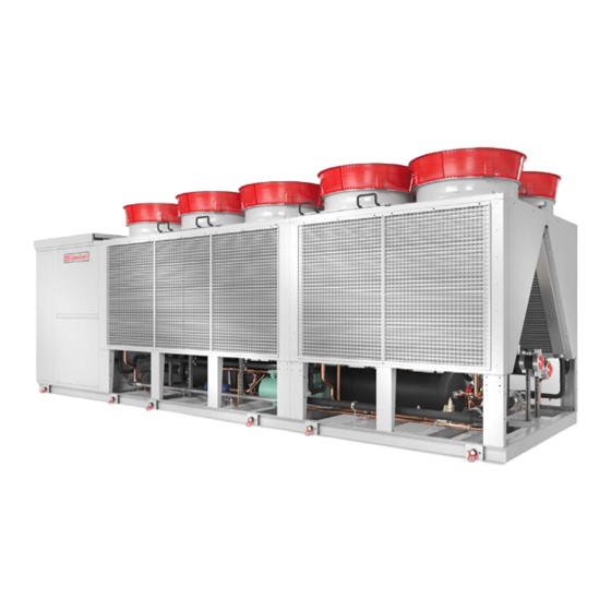
- Page 1 CyberCool 2 Original instructions Precision Chillers Screw compressor Index G41 400V/50Hz/3Ph/N/PE Issue 9.2019...
- Page 2 CY B E R CO O L 2 S C R E W O R I G I N A L I N S T R U C T I O N S A B O U T S T U L Z Since it was founded in 1947, the STULZ company has evolved into one of the world’s leading system suppliers of air-conditioning technology.
- Page 3 The high-end chiller Dear customer, we are pleased that you have decided for a CyberCool 2 Chiller from STULZ. The units, which were produced in Hamburg, have been developed especially for use in Data Cen- ters and industry and satisfy all requirements for efficiency and reliability.
- Page 4 CY B E R CO O L 2 S C R E W O R I G I N A L I N S T R U C T I O N S EN/09.2019/G41 © STULZ GmbH – all rights reserved...
-
Page 5: Table Of Contents
10. Contents of the CE Declaration of Conformity ..........94 11. Options ......................95 11.1 Option anti vibration mount ................... 95 11.2 Option AxiTop........................97 11.3 Option lateral power supply ..................99 11.4 Option anti-corrosion coating ................... 100 Subject to technical modifications. © STULZ GmbH – all rights reserved EN/09.2019/G41... -
Page 6: Safety
• Refrigerants have a narcotic effect when inhaled in high concentrations. • I f unavoidable work is required in the presence of a high concentration of refrigerant, breathing apparatus must be worn. This does not mean simple filter masks. Comply with breathing protection data sheet. • Do not eat, drink or smoke at work. • Warning against intentional misuse. • It is absolutely essential to comply with the first aid measures if accidents occur. • R efrigerants containing FCs contribute to the global warming and by this to climate changes. The EN/09.2019/G41 © STULZ GmbH – all rights reserved... -
Page 7: Duties Of The Operator
The operator is responsible for the execution. The operator must ensure that all maintenance, inspection and assembly work is carried out by authorized and qualified specialist staff who have made an in-depth study of the operating instructions. independent conversion and manufacture of replacement parts The system may only be converted or modified after consultation with STULZ. Original replacement parts and replacement parts/accessories authorized by STULZ are an aid to safety. © STULZ GmbH – all rights reserved EN/09.2019/G41... -
Page 8: Transport / Storage
• You receive the consignment papers with the delivery of the chiller unit. • The shipment is made ex works, in case of shipment damages, please assert your claim towards the carrier. 2.2 Storage If you put the unit into intermediate storage before the installation, the following measures have to be carried out to protect the unit from damage and corrosion: • t he storage point must not be exposed to direct sunlight. Observe the storage conditions in the chapter “Application limits“. • store the unit packaged to avoid the risk of corrosion. • m ake sure that the water connections are provided with protective hoods. EN/09.2019/G41 © STULZ GmbH – all rights reserved... -
Page 9: Transport
• After installation, remove the lifting lugs and keep them for future transport. notice • consider also the weight of the cross beams when you order the crane. • T he rope forces are higher than the weight forces according to the geometry. • Due to the risk of scratching the side planking, we advise, not to use chains. © STULZ GmbH – all rights reserved EN/09.2019/G41... - Page 10 4302 aSF 2680 6460 D must have the same length. eSo 4602 aSF 2681 6492 eSo 4302 aHn 2523 5881 eSo 4602 aHn 2525 5613 eSo 4302 aHF 2680 6480 eSo 4602 aHF 2681 6512 The co-ordinates of the centre of gravity are indicated with a tolerance of ± 50 mm. EN/09.2019/G41 © STULZ GmbH – all rights reserved...
- Page 11 7102 eSo 6602 a...F 2896 7991 eQo 4002 aSF 3220 7197 eQo 3002 aHF 3200 7047 The co-ordinates of the centre of gravity are indicated with eQo 3302 aHF 3230 7142 a tolerance of ± 50 mm. eQo 3702 aHF 3180 7131 eQo 4002 aHF 3220 7226 © STULZ GmbH – all rights reserved EN/09.2019/G41...
- Page 12 D must have the same length. eSo 6702 aSF 3382 8588 eSo 7102 aSF 3382 8658 eSo 6702 aHn 3170 7194 eSo 7102 aHn 3170 7265 eSo 6702 aHF 3382 8548 eSo 7102 aHF 3382 8619 The co-ordinates of the centre of gravity are indicated with a tolerance of ± 50 mm. EN/09.2019/G41 © STULZ GmbH – all rights reserved...
- Page 13 10880 eSo 9602 a...F 3081 10890 eQo 6602 aSF 3010 11070 eQo 4702 aHF 3470 9280 The co-ordinates of the centre of gravity are indicated with eQo 5102 aHF 3520 9443 a tolerance of ± 50 mm. eQo 6002 aHF 2970 10927 eQo 6602 aHF 3010 11107 © STULZ GmbH – all rights reserved EN/09.2019/G41...
- Page 14 9702 aSF 4049 11511 max. 2400 eSo 9802 aSF 4052 11661 eSo 9702 aHn 3759 9587 eSo 9802 aHn 3766 9739 eSo 9702 aHF 4049 11569 eSo 9802 aHF 4052 11721 The co-ordinates of the centre of gravity are indicated with a tolerance of ± 50 mm. 1150 EN/09.2019/G41 © STULZ GmbH – all rights reserved...
- Page 15 12602 a...F 4522 13236 eQo 9602 aSF 4620 12927 eQo 7402 aHF 4570 12553 The co-ordinates of the centre of gravity are indi- cated with a tolerance of ± 50 mm. eQo 8002 aHF 4630 12749 eQo 8702 aHF 4550 12791 G: unit transport weight eQo 9602 aHF 4620 12991 S: centre of gravity 1150 © STULZ GmbH – all rights reserved EN/09.2019/G41...
- Page 16 10202 a...n 4700 11413 eQo 11102 a...n 4620 11632 eQo 10202 aSF 5100 13803 eQo 11102 aSF 5030 14022 eQo 10202 aHF 5100 13874 eQo 11102 aHF 5030 14093 The co-ordinates of the centre of gravity are indicated with a tolerance of ± 50 mm. 1150 EN/09.2019/G41 © STULZ GmbH – all rights reserved...
- Page 17 At the delivery the chiller is equipped with flexible plates made of polypropylene, which are fixed at the condenser coils. If the unit is equipped with the option "coil protection grille" the protection grilles must be unscrewed to remove the polypropylene plates. • Remove these plates before start-up. Coil protection grille (optional) + housing protection grille (optional) option: coil protection grille The spacers are enclosed in the electrical cabinet. • Unscrew the coil protection grille (6 screws). • Remove the transport protection plates. • P lace the spacers (4 pieces each) on the protection grille. • Fix the coil protection grille. Spacer 6 x screw M6 4 x spacer © STULZ GmbH – all rights reserved EN/09.2019/G41...
-
Page 18: Description
A - air-cooled Number of refrigerant circuits: 2 - No. Nominal cooling capacity [kW] Installation: O - outside Sound version: S - standard Q - Quiet, low-noise Chiller type: E - screw compressor, DX EN/09.2019/G41 © STULZ GmbH – all rights reserved... -
Page 19: Intended Use
This chiller unit is used for the chilled water production and for the chilled water temperature control. The chill- er is designed for outdoor installation. Any use beyond this is not deemed to be use as intended. STULZ is not liable for any damage resulting from such misuse. - Page 20 Each refrigerant circuit disposes of the following safety devices: - low pressure switch - high pressure limiter with manual reset button at the housing - safety high pressure limiter with manual reset button in the housing - safety valve EN/09.2019/G41 © STULZ GmbH – all rights reserved...
- Page 21 The evaporated partial mass flow is drawn in by the compressor and added at an intermediate pressure level. The additional subcooling upstream the electronic expansion valve provides a higher exploitation of cooling capacity in the evaporator. © STULZ GmbH – all rights reserved EN/09.2019/G41...
- Page 22 Manueller Reset möglich bei manual reset possible at 18,0 Hochdruckbegrenzer High pressure limiter Auslösung bei releases at Manueller Reset möglich bei manual reset possible at 17,5 Sicherheitsventil Safety valve Auslösung bei releases at EN/09.2019/G41 © STULZ GmbH – all rights reserved...
-
Page 23: Technical Data
20 °C at maximum compressor capacity, water volume flow according to design conditions 18/12°C and outdoor temperature 35°C. The temperatures may vary during the start phase. • Set the water temperature setpoint consequently. © STULZ GmbH – all rights reserved EN/09.2019/G41... - Page 24 (a) full load at 18°C/12°C water temperature inlet/outlet (b) full load at 18°C/14°C water temperature inlet/outlet (min. dTw), outdoor temperature 35°C (c) full load at 18°C/10°C water temperature inlet/outlet (max. dTw), outdoor temperature 35°C EN/09.2019/G41 © STULZ GmbH – all rights reserved...
- Page 25 (a) full load at 18°C/12°C water temperature inlet/outlet (b) full load at 18°C/14°C water temperature inlet/outlet (min. dTw), outdoor temperature 35°C (c) full load at 18°C/10°C water temperature inlet/outlet (max. dTw), outdoor temperature 35°C © STULZ GmbH – all rights reserved EN/09.2019/G41...
- Page 26 Max. outdoor temperature (a) °C °C 56,7 59,1 56,9 57,8 55,3 57,3 54,9 max. Wasservolumenstom (b) max. water volume flow (b) m³/h m³/h min. Wasservolumenstom (c) min. water volume flow (c) m³/h m³/h EN/09.2019/G41 © STULZ GmbH – all rights reserved...
- Page 27 Electric conductivity without inhibitors µS/cm 10 - 500 Electric conductivity with inhibitors µS/cm <2200 cfu - colony forming units *aluminium or titanium. All data refer exclusively to the chiller. NOtICE • Check the water quality regularly. © STULZ GmbH – all rights reserved EN/09.2019/G41...
-
Page 28: Technical Data
(4): Water inlet temperature 18°C, glycol content 30%, outdoor temperature 6°C * 1st part-winding # star connection Transport weight = net weight + weight of refrigerant charge Operating weight = transport weight + weight of water content EN/09.2019/G41 © STULZ GmbH – all rights reserved... - Page 29 2300 2300 2300 Höhe Height 2510 2510 2510 Baugröße Construction size 1½ 2½ Transportgewicht Transport weight 5561 5593 6024 6113 6736 6831 7234 Betriebsgewicht Operating weight 5964 5996 6477 6566 7196 7291 7735 © STULZ GmbH – all rights reserved EN/09.2019/G41...
- Page 30 2300 2300 Höhe Height 2510 2510 2510 Baugröße Construction size 2½ 3½ Transportgewicht Transport weight 7304 8023 8199 9017 9221 9528 9679 Betriebsgewicht Operating weight 7805 8796 8972 9821 10025 10333 10484 EN/09.2019/G41 © STULZ GmbH – all rights reserved...
- Page 31 Länge Length 11640 12785 Breite Width 2300 2300 Höhe Height 2510 2510 Baugröße Construction size Transportgewicht Transport weight 10649 10865 10889 11111 11529 11753 Betriebsgewicht Operating weight 12142 12358 12444 12666 13152 13376 © STULZ GmbH – all rights reserved EN/09.2019/G41...
- Page 32 2300 2300 Höhe Height 2510 2510 2510 Baugröße Construction size 1½ 2½ Transportgewicht Transport weight 6460 6492 7185 7274 7896 7991 8588 Betriebsgewicht Operating weight 7138 7170 7999 8087 8717 8811 9465 EN/09.2019/G41 © STULZ GmbH – all rights reserved...
- Page 33 2300 2300 2300 Höhe Height 2510 2510 2510 Baugröße Construction size 2½ 3½ Transportgewicht Transport weight 8658 9693 9869 10687 10890 11511 11661 Betriebsgewicht Operating weight 9535 11032 11207 12057 12260 12922 13072 © STULZ GmbH – all rights reserved EN/09.2019/G41...
- Page 34 Length 11640 12785 Breite Width 2300 2300 Höhe Height 2510 2510 Baugröße Construction size Transportgewicht Transport weight 12775 12990 13015 13236 13990 14213 Betriebsgewicht Operating weight 15067 15282 15369 15591 16519 16742 EN/09.2019/G41 © STULZ GmbH – all rights reserved...
- Page 35 2300 2300 2300 Höhe Height 2510 2510 2510 Baugröße Construction size 1½ 2½ Transportgewicht Transport weight 5581 5613 6025 6114 6736 6831 7194 Betriebsgewicht Operating weight 5983 6015 6478 6567 7196 7290 7694 © STULZ GmbH – all rights reserved EN/09.2019/G41...
- Page 36 2300 2300 Höhe Height 2510 2510 2510 Baugröße Construction size 2½ 3½ Transportgewicht Transport weight 7265 8024 8199 9017 9221 9587 9739 Betriebsgewicht Operating weight 7766 8796 8971 9821 10025 10392 10544 EN/09.2019/G41 © STULZ GmbH – all rights reserved...
- Page 37 Länge Length 11640 12785 Breite Width 2300 2300 Höhe Height 2510 2510 Baugröße Construction size Transportgewicht Transport weight 10649 10864 10889 11111 11529 11753 Betriebsgewicht Operating weight 12142 12357 12444 12666 13152 13375 © STULZ GmbH – all rights reserved EN/09.2019/G41...
- Page 38 2300 2300 Höhe Height 2510 2510 2510 Baugröße Construction size 1½ 2½ Transportgewicht Transport weight 6480 6512 7185 7274 7896 7991 8548 Betriebsgewicht Operating weight 7158 7190 7999 8087 8717 8811 9425 EN/09.2019/G41 © STULZ GmbH – all rights reserved...
- Page 39 2300 2300 2300 Höhe Height 2510 2510 2510 Baugröße Construction size 2½ 3½ Transportgewicht Transport weight 8619 9693 9869 10687 10890 11569 11721 Betriebsgewicht Operating weight 9496 11032 11207 12057 12260 12980 13132 © STULZ GmbH – all rights reserved EN/09.2019/G41...
- Page 40 Length 11640 12785 Breite Width 2300 2300 Höhe Height 2510 2510 Baugröße Construction size Transportgewicht Transport weight 12775 12990 13015 13236 13990 14213 Betriebsgewicht Operating weight 15067 15282 15369 15591 16519 16742 EN/09.2019/G41 © STULZ GmbH – all rights reserved...
- Page 41 7250 9480 Breite Width 2300 2300 Höhe Height 2510 2510 Baugröße Construction size Transportgewicht Transport weight 5887 5982 5971 6066 7610 7773 9257 Betriebsgewicht Operating weight 6273 6368 6354 6449 8104 8267 9790 © STULZ GmbH – all rights reserved EN/09.2019/G41...
- Page 42 Width 2300 2300 2300 Höhe Height 2510 2510 2510 Baugröße Construction size Transportgewicht Transport weight 9437 10427 10623 10665 10865 11413 11632 Betriebsgewicht Operating weight 9970 11270 11466 11580 11780 12964 13183 EN/09.2019/G41 © STULZ GmbH – all rights reserved...
- Page 43 7250 9480 Breite Width 2300 2300 Höhe Height 2510 2510 Baugröße Construction size Transportgewicht Transport weight 7018 7103 7102 7197 9233 9396 10880 Betriebsgewicht Operating weight 7765 7850 7846 7941 10293 10456 11978 © STULZ GmbH – all rights reserved EN/09.2019/G41...
- Page 44 Width 2300 2300 2300 Höhe Height 2510 2510 2510 Baugröße Construction size Transportgewicht Transport weight 11070 12489 12695 12727 12927 13803 14022 Betriebsgewicht Operating weight 12168 14132 14338 14441 14641 16260 16479 EN/09.2019/G41 © STULZ GmbH – all rights reserved...
- Page 45 7250 9480 Breite Width 2300 2300 Höhe Height 2510 2510 Baugröße Construction size Transportgewicht Transport weight 5887 5982 5971 6066 7610 7773 9257 Betriebsgewicht Operating weight 6273 6368 6354 6449 8104 8267 9790 © STULZ GmbH – all rights reserved EN/09.2019/G41...
- Page 46 Width 2300 2300 2300 Höhe Height 2510 2510 2510 Baugröße Construction size Transportgewicht Transport weight 9437 10427 10623 10665 10865 11413 11632 Betriebsgewicht Operating weight 9970 11270 11466 11580 11780 12964 13183 EN/09.2019/G41 © STULZ GmbH – all rights reserved...
- Page 47 7250 9480 Breite Width 2300 2300 Höhe Height 2510 2510 Baugröße Construction size Transportgewicht Transport weight 7047 7142 7131 7226 9280 9443 10927 Betriebsgewicht Operating weight 7794 7889 7875 7970 10339 10502 12026 © STULZ GmbH – all rights reserved EN/09.2019/G41...
- Page 48 Width 2300 2300 2300 Höhe Height 2510 2510 2510 Baugröße Construction size Transportgewicht Transport weight 11107 12553 12749 12791 12991 13874 14093 Betriebsgewicht Operating weight 12205 14196 14392 14505 14705 16331 16550 EN/09.2019/G41 © STULZ GmbH – all rights reserved...
-
Page 49: Dimensional Drawings
2 s c r e w o r i g i n a l i n s T r U c T i o n s 4.3 Dimensional drawings Construction size 1½ 2300 6170 Construction size 2 7250 2300 Construction size 2½ 8330 2300 Construction size 3 2300 9480 © STULZ GmbH – all rights reserved EN/09.2019/G41... - Page 50 2 s c r e w o r i g i n a l i n s T r U c T i o n s EN/09.2019/G41 © STULZ GmbH – all rights reserved...
-
Page 51: Installation
NOtICE Screwed pipe joints can loosen by long transportation distances. • Before final commissioning, check all screwed pipe joints in the refrigerant circuit and chilled water circuit on tightness. © STULZ GmbH – all rights reserved EN/09.2019/G41... - Page 52 Keep a clearance of 1 m around the unit to every side. • Above the fans a clearance of 2,5 m is required. Maintenance clearance Space needed for individual installation and multiple unit installation EN/09.2019/G41 © STULZ GmbH – all rights reserved...
-
Page 53: Weights On The Supports
ESO 4302 AHN ESO 4602 AHN The weights are indicated with a tolerance of ±5%. The weight on the support Mxr (M1, M2, M3 ... M5) is equal to the weight on the support Mxl. © STULZ GmbH – all rights reserved EN/09.2019/G41... - Page 54 EQO 4002 A...F 1023 1050 The weights are indicated with a tolerance of ±5%. The weight on the support Mxr (M1, M2, M3 ... M5) is equal to the weight on the support Mxl. EN/09.2019/G41 © STULZ GmbH – all rights reserved...
- Page 55 ESO 6702 AHN ESO 7102 AHN The weights are indicated with a tolerance of ±5%. The weight on the support Mxr (M1, M2, M3 ... M6) is equal to the weight on the support Mxl. © STULZ GmbH – all rights reserved EN/09.2019/G41...
- Page 56 1042 1054 1000 The weights are indicated with a tolerance of ±5%. The weight on the support Mxr (M1, M2, M3 ... M6) is equal to the weight on the support Mxl. EN/09.2019/G41 © STULZ GmbH – all rights reserved...
- Page 57 ESO 9802 AHN 1135 The weights are indicated with a tolerance of ±5%. The weight on the support Mxr (M1, M2, M3 ... M7) is equal to the weight on the support Mxl. © STULZ GmbH – all rights reserved EN/09.2019/G41...
- Page 58 1068 1068 1021 The weights are indicated with a tolerance of ±5%. The weight on the support Mxr (M1, M2, M3 ... M7) is equal to the weight on the support Mxl. EN/09.2019/G41 © STULZ GmbH – all rights reserved...
- Page 59 2 s c r e w o r i g i n a l i n s T r U c T i o n s Construction size 5 © STULZ GmbH – all rights reserved EN/09.2019/G41...
-
Page 60: External Water Circuit
If you connect two or more chillers in parallel, we recommend to install regulating valves to keep the pressure drop of each unit equally high. return water flow water Chiller 1 Chiller 2 EN/09.2019/G41 © STULZ GmbH – all rights reserved... - Page 61 • 3/4 turn counterclockwise. • Remove crank handle and turn latch to the side. • Put the crank handle in the provided opening again and move the valve disc by means of the crank handle. © STULZ GmbH – all rights reserved EN/09.2019/G41...
- Page 62 ±10 mm. To avoid misunderstanding: The designation "water inlet" and "water outlet" are chosen, seen from the chiller. At the water outlet, the chilled water is provided from the chiller. EN/09.2019/G41 © STULZ GmbH – all rights reserved...
- Page 63 • Remove the protective hoods from the water pipes. • Connect the external piping to the chilled water lines of the chiller free of mechanical stress. © STULZ GmbH – all rights reserved EN/09.2019/G41...
-
Page 64: Electrical Connection
ESD NOtE Do not touch electronical components, without taking care of protective ESD measures. Electronical components: - C7000 IO controller (1) EN/09.2019/G41 © STULZ GmbH – all rights reserved... - Page 65 (part of the unit documents). • secure these cables by the pull relief screw. © STULZ GmbH – all rights reserved EN/09.2019/G41...
- Page 66 Connection of control lines (optional) If the chiller shall be connected to other Stulz units by the IO bus, to a BMS or contains opional extensions, you must route control lines and connect them in the electric cabinet of the chiller.
- Page 67 • Design the wiring between the controller and the contactor with reference to the connection diagram for the controller and the wiring between the pump and power switch according to the manufacturer's notes. © STULZ GmbH – all rights reserved EN/09.2019/G41...
-
Page 68: Commissioning
Lethal dose: 0,4 g ethylene glycol/kg body weight, severe intoxication: already at 0,1 ml/kg. Glycol is absorbed through the skin. Therefore immediately change clothing soaked with glycol. Wear protective gloves made of rubber. EN/09.2019/G41 © STULZ GmbH – all rights reserved... - Page 69 Deventilation valves Rubber plug to cover the vent valve openings Rubber plugs and blee- ding line in a chiller with free cooling (on this illustration the condenser fans are not yet installed.) © STULZ GmbH – all rights reserved EN/09.2019/G41...
-
Page 70: Control Of The Electrical Box
• Switch on the control-circuit fuses. The compressor power switches may not yet be switched on. • Switch on the chiller unit at the master switch. The oil heater and the controller are now supplied with power, so you can use it for adjustments. EN/09.2019/G41 © STULZ GmbH – all rights reserved... - Page 71 2 Condenser fan power switch circuit 1 Compressor Compressor power switch power switch circuit 2 circuit 1 Compressor power switch Main switch in position "off" Neutral terminal PE rail Power supply © STULZ GmbH – all rights reserved EN/09.2019/G41...
- Page 72 „state stop“ command), the expansion valve is closed using the battery. When the bat- tery is discharged, the valve in this case retains its current opening degree. The open expansion valve allows liquid refrigerant to flow into the evaporator. EN/09.2019/G41 © STULZ GmbH – all rights reserved...
- Page 73 • Press the "P" key. The set value and "SP" will be displayed alternately. • Adjust new setpoint by the keys. • Press "P" key to return to the display of the actual value. The hysteresis is fixed to 5 Kelvin. © STULZ GmbH – all rights reserved EN/09.2019/G41...
-
Page 74: Control Of Pressure Switch Setting
• In the meantime the laptop can be switched off and the connection to the I/O controller can be separated. • Keep the pump running for 8 hours and clean the implemented filter (recommended part of the external cir- cuit) after this lapse of time. EN/09.2019/G41 © STULZ GmbH – all rights reserved... -
Page 75: Commissioning Of The Refrigerant Circuits
45 degrees. The oil level should be between the lower quarter and the upper quarter of the sight glass. © STULZ GmbH – all rights reserved EN/09.2019/G41... - Page 76 • Perform the same checks as for the first refrigerant circuit. • Switch off the manual mode for all components. handoff • Instruct the operational staff of the controller manipulation (refer to the C7000 controller manual). EN/09.2019/G41 © STULZ GmbH – all rights reserved...
- Page 77 : minimum cycle time of compressor Command: comp 1 mincycle 900 Compressor operation min idle time min runtime min cycle time unit types Pause E_O 3002 to E_O 5102 E_O 6002 to E_O 14102 © STULZ GmbH – all rights reserved EN/09.2019/G41...
-
Page 78: Maintenance
Water circuit Tightness Evaporator Unit housing Electrical box Unit interior ** depending on environment, in the proximity of trees and in case of low positioning of the chiller, a half-yearly control is required. EN/09.2019/G41 © STULZ GmbH – all rights reserved... -
Page 79: Refrigerant Circuit
Bubbles in the sight glass indicate that the charge is insufficient or that the filter drier is clogged. A pollution of the filter drier, whose essential task is to clear the refrigerant from impurities and humidity, can be detected by a temperature difference upstream and downstream the filter drier. • Compare the colour indicator in the centre of the sight glass with the outer ring scale. © STULZ GmbH – all rights reserved EN/09.2019/G41... - Page 80 Exchange of the filter drier To exchange the filter drier it is sufficient to evacuate the pipe section in which the filter drier is installed. • C lose the shut off valve at the liquid receiver and the valve in the liquid line upstream the expansion valve. • B y the service valve on the lid of the filter drier, you can evacuate the refrigerant from the section. • Remove eight M8 screws at the front side and pull out the cartridge. Filter drier, service valve • Introduce a new cartridge and refill the evacuated refrigerant. • Open the shut off valves. EN/09.2019/G41 © STULZ GmbH – all rights reserved...
- Page 81 LP switch with scale for threshold and pressure having removed the adjustment lock. One turn approximately hysteresis for automatic reset corresponds to a threshold change by 1,6 bar. After the compressor pause (default setting: 180 sec.) has elapsed the compressor is restarted. During the evaluation © STULZ GmbH – all rights reserved EN/09.2019/G41...
- Page 82 If you can find no deviation at all checks, probably the control module of the valve is defective and must be replaced. The expansion valve can freeze, if the humidity in the refrigerant circuit is excessive. dAngER do not thaw by soldering flame, danger of explosion ! Thaw with moist warm cloth. Check the sight glass. EN/09.2019/G41 © STULZ GmbH – all rights reserved...
- Page 83 100.000 Check valve 5.000* 20.000 ... 40.000 Roller bearing 10.000 50.000 *at least yearly check Screw compressor, sectional view hot gas line connection suction line connection (3) oil sight glass (2) oil service valve oil heater (1) oil drain plug © STULZ GmbH – all rights reserved EN/09.2019/G41...
- Page 84 4. C onnect the clean oil container by a pipe to the oil service valve (2) in the lower middle section of the compressor. 5. Open the oil service valve and lift the oil container so that the oil flows into the compressor by gravity. 6. F ill in the required quantity of oil. Ensure that the supply line is always below the oil level. (to avoid the introduc- tion of air bubbles in the pipe) The oil level should be in the lower quarter of the oil sight glass (3). 7. C lose the oil service valve, open the shut-off valves of the compressor and recharge the collected refrigerant into the refrigerant circuit. (3) oil sight glass max. oil temperature sensor oil heater oil level sensor (2) oil service valve EN/09.2019/G41 © STULZ GmbH – all rights reserved...
-
Page 85: Air Circuit
For coated finned heat exchangers and microchannel coils, we recommend a cleaning with just warm water without using chemicals. Procedure • first clean the coil with a vacuum cleaner and soft nozzle. • rinse from the inside out and from bottom to top. • direct the jet of water always vertically on the fins, to not distort the fins. • allow the detergent to react on the debris about 1-5 minutes, but do not let it dry. For rinsing, we recommend to use a high pressure washer with hot water of 50-80 °C. Rinsing with cold water is less effective. • rinse all wetted surfaces thoroughly. • rinse the debris from the inside out and from bottom to top, until the exiting water is completely clean. • d rain the water which has accumulated between the coils by removing the plugs at the bottom plate. We accept no liability for consequential damages and improper application. © STULZ GmbH – all rights reserved EN/09.2019/G41... - Page 86 • disconnect the electrical connections and protect them against damage and humidity. • completely unscrew the 4 Torx screws of the fan grille • lift the fan (weight: approx. 30 kg) with another person and place it upside down on a fan next to it. Condenser fan The bearings of the fans are lifetime lubricated and do not need maintenance. Check the operation current. An increased operation current indicates a winding short circuit in the fan motor. Air filter in the compressor cabinet • Check the filter in the air intake / outlet (see figure on page 21) in terms of pollution (visual inspection). • R eplace the filters (filter class G3) if necessary. The grilles are held by plastic clips and can be removed using a screwdriver. EN/09.2019/G41 © STULZ GmbH – all rights reserved...
-
Page 87: Water Circuit
Another possibility to verify this, consists in the comparison of the chilled water outlet temperature with the saturated evaporation temperature (by measuring the suction pressure at the low pressure side of the com- pressor). If this difference exceeds 7 K, the evaporator is probably polluted. In this case the evaporator has to be cleaned chemically. Frost protection sensor Flow sensor Water outlet temperature sensor Water inlet temperature sensor Chilled water sensors Pump (option) The pump is equipped with permanently lubricated bearings. According to the manufacturer's instructions, the bearings have an expected durability of 20,000 operating hours. • check the pump for audible and visible wearing. • replace the bearings with noticeable wearing. • f or instructions on how to replace the bearing see QR-code on the pump or instruction sheet in the e Stulz area. © STULZ GmbH – all rights reserved EN/09.2019/G41... -
Page 88: Unit Housing
At the fan contactor, dangerous voltages occur. Do not open the unit within the first 5 minutes after disconnection of all phases. Due to the EC fans dangerous charges of >50µC can occur for a short time between AC line terminals and PE after disconnection. Electrical box • c heck the connection terminals for tight fixation when the unit is installed and once again after an operation time of 30 days. CAUTIOn The power contactors of the compressors must be checked on smooth operation and worn contacts every 10 years. Unit interior Clean pipes simplify the search for leaks. Vibrations of pipes and circuit components can result in leaks. • check the pipes for a tight seat. Condensing air humidity on cold water pipes means a loss of cooling capacity. • check the insulation of the water piping. EN/09.2019/G41 © STULZ GmbH – all rights reserved... -
Page 89: Malfunction
EEV #: Temperature The control module has detect- 1. Cable breakage or faulty contact Check cable and contacts. sensor error ed a malfunction of the temper- ature sensor. 2. Temperature sensor defective. Replace temperature sensor. # stands for a number in case of several components of the same kind. © STULZ GmbH – all rights reserved EN/09.2019/G41... - Page 90 Comp. prot. device....:0 5: C ritical (pressure ratio is located in the area bet- envelope left.....:1 ween blue and red line in the chart.) Alarm......:0 6: F ault (pressure ratio is located out of the red line Alarm low press....:0 or longer than 30 seconds between blue and red line.) Envelope zones: 0: Pressure conditions ok. 1: Suction pressure too low, Hot gas pressure too low 2: Suction pressure too low, Hot gas pressure ok 3: Suction pressure too low, Hot gas pressure too high 4: Suction pressure ok, Hot gas pressure too high 5: Suction pressure too high, Hot gas pressure too high 6: Suction pressure too high, Hot gas pressure ok 7: Suction pressure too high, Hot gas pressure too low 8: Suction pressure ok, Hot gas pressure too low Suction gas pressure EN/09.2019/G41 © STULZ GmbH – all rights reserved...
- Page 91 No voltage is present at the 1. An external device has triggered Depending on the type of message. failure digital input for the external a signal. alarm #. 2. Cable breakage or faulty contact. Check wiring. # stands for a number in case of several components of the same kind. © STULZ GmbH – all rights reserved EN/09.2019/G41...
- Page 92 1 0 0 0 In this case the circuit breaker has also triggered Alarm availability...:1 1 1 0 0 and cut off three fans, which are therefore no longer reachable via Modbus. The fans with the addr. 101, 102,103 can not be reached. EN/09.2019/G41 © STULZ GmbH – all rights reserved...
-
Page 93: Dismantling And Disposal
• d isconnect the unit from the external water circuit by closing the external shut-off valves and drain the water circuit of the unit. • disconnect the depressurized chilled water pipes of the unit from the external system. • m ove the unit, as described in the chapter „transport“, with a lifting device of sufficient load-carrying capacity. • dispose of the chiller in accordance with the disposal and safety regulations applicable on site. We recommend a recycling company for this. The unit basically contains the raw materials aluminium (heat exchanger coils), copper (pipelines, wiring), iron (panelling, frames) and P235 steel (water piping). The electrical and electronical components installed in the electric cabinet must be separately disposed of according to the European directive 2012/19/EU. The concerned components are marked by the symbol of the crossed-out wheeled bin. © STULZ GmbH – all rights reserved EN/09.2019/G41... -
Page 94: Contents Of The Ce Declaration Of Conformity
Name of notified body for inspection and monitoring DNV GL AS of the Production Quality Assurance: Veritasveien 1 1322 Høvik, Norway national regulation Harmonised En EC-directives BGR 500 chapter 2.35 EN 378 -1, -2, -3, -4 EC machinery directive 2006/42/EC BGV A3 EN ISO 12100 EC directive for low voltage 2014/35/EU EN ISO 13857 EC EMC directive 2014/30/EU EN 60204 -1 RoHS directive 2011/65/EU EN 61000-6-2 Energy-related products directive 2013/12/EU EN 61000-6-4 2019 Year of manufacture: EN/09.2019/G41 © STULZ GmbH – all rights reserved... -
Page 95: Options
The anti-vibration mounts protrude the lateral dimensions of the chiller by 59 mm. Base plate of anti-vibration mount Number of anti-vibration mounts per unit size Baugröße Size 1½ 2½ 3½ Anzahl Number 12,5 Example: unit size 2 © STULZ GmbH – all rights reserved EN/09.2019/G41... - Page 96 • Keep in mind that the anti-vibration mounts under load yield up to 4 mm in height. • Now position the chiller on the provided support frame and fasten the anti-vibration mounts on this frame. wedge plate washer EN/09.2019/G41 © STULZ GmbH – all rights reserved...
-
Page 97: Option Axitop
The eight screws may be tightened with a torque of 9 Nm ± 1,4 Nm. external diffusor internal diffusor support ring cable cut-outs connection cables © STULZ GmbH – all rights reserved EN/09.2019/G41... - Page 98 If the fan is entirely exchanged (not only the motor) it is appropriate to reuse the support ring at which the cooling tube is attached. cooling tube plastic clip EN/09.2019/G41 © STULZ GmbH – all rights reserved...
-
Page 99: Option Lateral Power Supply
With this option you can feed in the power supply cables from the right or left side. All sizes Feed in from right max. 3 x Ø65 Feed in from left max. 3 x Ø65 © STULZ GmbH – all rights reserved EN/09.2019/G41... -
Page 100: Option Anti-Corrosion Coating
When using the anti-corrosion coating the cooling capacity specified in the technical data is reduced by 5-10%. The airside pressure loss increases by 0 - 5%. EN/09.2019/G41 © STULZ GmbH – all rights reserved... - Page 102 2 o r i g i n a l i n S T r U c T i o n S STULZ Top Service – more than just quick emergency assistance Technical manage-...
Need help?
Do you have a question about the CyberCool 2 and is the answer not in the manual?
Questions and answers