
Subscribe to Our Youtube Channel
Related Manuals for Shire 7x5 Value Overlap


Summary of Contents for Shire 7x5 Value Overlap
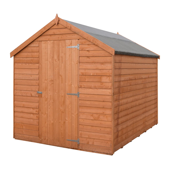
- Page 1 © 7x5 Value Overlap These instructions are for your safety. Please read through them thoroughly before use. PLEASE KEEP THIS LEAFLET FOR FUTURE REFERENCE...
-
Page 2: Table Of Contents
Let’s get started... Important information... Safety Preparation of base Warranty Care, maintenance & Recycling In more detail... Parts List Fascia & Nail List Hardware chart Before you start Detailed Technical Drawing 10-11 Assembly instructions 12-24 For a copy of the instructions or a copy in another language please send an email or write to the address below. -
Page 3: Safety
Safety Check that you have noted all the following instructions: We advise the use of non slip protective gloves throughout the assembly process. We advise the use of steel capped protective footwear throughout the assembly process. We advise that you use a helper to hold the glass in position whilst you nail the beading in place. -
Page 4: Preparation Of Base
Base and Warranty Preparation of base... We recommend that the base onto which your building will stand should be at least 75mm larger in each direction than the total floor size of the building. Actual floor area of the building: 2048mm x 1618mm ... -
Page 5: Care, Maintenance & Recycling
Care, Maintenance and Recycling The 5 golden rules of care: Ensure your base is level and firm. Ensure the building is not sitting directly on the ground using damp proof membrane or the optional timber base. Ensure every piece of timber and surface, especially that is hidden upon assembly is treated with a top quality wood preservative at least twice (before assembly). -
Page 6: Parts List
Stacked Parts List Description (part No ) - Qty... -
Page 7: Fascia & Nail List
Stacked Parts List Description (part No ) - Qty Nail Bag Parts List Description (part No ) - Qty... -
Page 8: Hardware Chart
Nail bag contents Description (part No ) - Qty Hardware Chart Scale 1:1 8mm Felt Nail (A0266) x116 40mm Round head nail (A0025) x89 25mm Posi-drive screw (A0032) x27 60mm Posi-drive screw (A0035) x26... -
Page 9: Before You Start
Before you start... Things to check before you start: Ensure your base is ready – See page 4 Check all parts as listed in the parts lists Read the instructions fully before starting work Follow all the health and safety guidelines. When you see the drill icon Only ever drill through the first piece of framework which will be a... -
Page 12: Assembly Instructions
Assembly instructions: These instructions are for your safety. Please read through them thoroughly before use. Treat all the parts before assembly – see page 5! GB-IE The door end panels and the opposite end panels FIT INSIDE THE SIDE PANELS! A4763 Floor panel (A1555)x02... - Page 13 Drill one “A4762” plain end as shown GB-IE A Plain panel "A4763" for the side goes into the corner of the floor. Filling the entire floor length. Mark this panel where the floor bearers are (inline with nails) and drill. The cladding overlaps the floor, push the plain end "A4762"...
- Page 14 Drill the “A4761 Door Panel”, slide it into position and fix as with the other end. GB-IE Door Panel (A4761) x01 60mm Screws (A0035)x03...
- Page 15 Drill one “A4763” panel again marking to ensure the bottom hole s are in line with a floor bearers. GB-IE Plain Panel (A4763) x01 60mm Screws (A0035)x03 Inline with floor bearers...
- Page 16 Position the roof edging “A4764” under and flush with the long edge of the roof panels "A4733 " filling GB-IE the whole length and fix with 5 40mm nails. Position a roof bearer “A1562” under the opposite edge with an even gap at either end(8mm) and fix as above.
- Page 17 The roof edge that runs the full length of the roof panel is positioned at the low edge off the roof outside GB-IE the walls. The shorter roof bearer on the opposite edge of the roof sheet drops into the w shape and against the block at the high point of the roof,.
- Page 18 RIGHT HAND HUNG DOOR POSITION SHOWN GB-IE Align the A2456 hinge strip flush with the inside face of the doorway framework (widest side against framework )and fix with 40mm nails. 46mm Hinge Strip (A2546)x01 40mm Nails (A0025)x04 Building Photographs It will be greatly A2546 appreciated if you could FIT THIS TO THE...
- Page 19 GB-IE Fix the hinges as shown so the screws go into the horizontal framework on the back of the door Ensure The hinge is over the framework gap on the back of the door. Hinge over door Door framework (A4420)x 01 INSIDE VIEW Tee hinge (A0049)x03...
- Page 20 Fit the door stop-sides “A4421” then the door stop “A4449” flush with the outside edge of the GB-IE framework not the cladding. Nail with 3x40mm fort the top and 4x40mm nails each side. 28mm Door Stop-Top (A4449)x 01 28mm Door Stop-sides (A4421)x02 25mm screws (A0032)x24...
- Page 21 Make sure everything is square and true GB-IE Fix the walls to the floor with 60mm screws using the holes drilled previously. 60mm Screws (A0035)x10 GB-IE Fit cover strips at each corner with 4 nails each. 48mm Rustic Cover strip (A4040) x04 40mm Nails (A0025)x16...
- Page 22 3 Strips of felt have been supplied . GB-IE Fit the 2 lower strips first folding the felt over the roof edging, with an even overhang front and back then secure with a couple of nails at the top to hold the felt in position and at the bottom nail at approximately100mm centres.
- Page 23 The third piece overlaps the lower pair and goes over the ridge. GB-IE Nail at approximately100mm centres 2.3m Felt strips (A1353))x01 08mm Felt nails (A0266) x50...
- Page 24 GB-IE Drill and fix the Fascia's with 3 nails each and the diamonds with 2 nails each. Drill 1mm pilot holes to prevent the diamonds from splitting. 1 mm Fascia (A4765)x04 Diamond (A0019)x02 40mm Nails (A0025)x16...
Need help?
Do you have a question about the 7x5 Value Overlap and is the answer not in the manual?
Questions and answers