Table of Contents
Advertisement
Quick Links
Advertisement
Table of Contents

Related Manuals for ATI Technologies Radeon CrossFire X850


Summary of Contents for ATI Technologies Radeon CrossFire X850
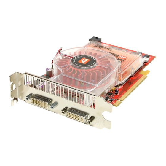
- Page 1 ® Radeon X850 ™ CrossFire Edition User’s Guide P/N 137-40863-10...
- Page 2 ATI hardware, software, or other products and documentation provided herein. ATI Technologies Inc. reserves the right to make changes without further notice to a product or system described herein to improve reliability, function or design. With respect to ATI...
- Page 3 IMPORTANT SAFETY INSTRUCTIONS • Read Instructions - All the safety and operating instructions should be read before the product is operated. • Retain Instructions - The safety and operating instructions should be retained for future reference. • Heed Warnings - All warnings on the product and the operating instructions should be adhered to.
-
Page 5: Table Of Contents
Table of Contents CrossFire™ FAQ ......1 Welcome to CrossFire™ ..... 7 CrossFire™... - Page 6 Software Installation Prerequisites Monitor Configuration Reinstalling Drivers Installing the Catalyst™ Software Suite Catalyst™ Control Center ....35 Launching Catalyst™ Control Center Launching Catalyst™ Control Center Using the Start Menu Other Quick Launch Access Points Help Displays Manager...
- Page 7 Index ........75...
- Page 8 viii...
-
Page 9: Crossfire™ Faq
CHAPTER 1: CrossFire™ FAQ The following is a listing of frequently-asked questions about CrossFire™. For the latest information, please consult the CrossFire™ Web site at: ati.com/crossfire What combination of products are required to build a working CrossFire™ system? Three components are required: •... - Page 10 Which slot does the CrossFire™ Master card go into on the motherboard? The CrossFire™ Master card must go into the primary PCI Express® slot (slot zero) on the motherboard. Note: To determine which PCIe™ slot is the primary slot, consult your motherboard manual.
- Page 11 To access and enable CrossFire™ in Catalyst™ Control Center, do the following: • Click CrossFire™ in Advanced View. Then, select Enable CrossFire™. When CrossFire™ is successfully enabled, all display devices except the one used by CrossFire™ will be disabled. Multiple monitors/ displays that are disabled when CrossFire™...
- Page 12 graphics card. The result is a complete frame rendered at up to twice the performance of a single graphics card. How are the graphics cards connected on a CrossFire™ system? The two cards are connection by an external cable. The cable is attached from the Slave graphics card’s DVI-I connection to the CrossFire™...
- Page 13 • Scissor Mode - each graphics card renders up to half of the display, either vertically or horizontally depending on the game or application. • Alternate Frame Rendering - the two graphics cards are used to render alternate frames of the display. This configuration increases the detail of the 3D objects each card can render, as each card handles half of the total number of frames.
- Page 14 of those displays as a dedicated CrossFire™ display. If the motherboard contains an integrated video connection and SurroundView™ is enabled, more displays can be added. Additional issues are covered in the “Troubleshooting” chapter in the User’s Guide.
-
Page 15: Welcome To Crossfire
CrossFire™ Overview 7 CHAPTER 2: Welcome to CrossFire™ ATI's CrossFire™ propels gaming PCs with the ultimate multi-GPU consumer graphics solution. CrossFire™ Overview This section provides an overview of the main features and configurations for CrossFire™. These topics will be covered in more detail in other chapters of this manual. -
Page 16: Supertiling
8 CrossFire™ Rendering Modes • Alternate Frame Rendering • Super Anti-aliasing. The first three are performance-oriented modes, and Super Anti-aliasing is a quality-oriented mode. Each mode uses a different method for dividing the workload required to render a 3D image across multiple GPUs. Only one mode can be in operation at any given time. -
Page 17: Scissor Mode
CrossFire™ Rendering Modes 9 PCI Express® Slave Graphics Card Radeon® X850 CrossFire Edition Master Graphics Card Partial Frame Rendered on PCI Express® Slave Graphics Card Partial Frame Rendered on PCI Express® Master Graphics Card Final Rendered Frame on Display SuperTiling has the advantage of being able to work with practically any 3D application. -
Page 18: Alternate Frame Rendering (Afr) Mode
10 CrossFire™ Rendering Modes PCI Express® Slave Graphics Card Radeon® X850 CrossFire Edition Master Graphics Card Partial Frame Rendered on PCI Express® Slave Graphics Card Partial Frame Rendered on PCI Express® Master Graphics Card Final Rendered Frame on Display Although Scissor Mode is generally a less efficient means of splitting the workload than using SuperTiling, there are a few cases where it can be more efficient. -
Page 19: Super Anti-Aliasing Mode
CrossFire™ Rendering Modes 11 improvements of all the available modes. It is also the only mode that allows the full vertex processing performance of both GPUs to be combined. PCI Express® Slave Graphics Card Radeon® X850 CrossFire Edition Master Graphics Card Partial Frame Rendered on PCI Express®... - Page 20 12 CrossFire™ Rendering Modes 3D images. Rather than simply determining the color of each pixel on the screen by sampling a single location at the pixel’s center, anti-aliasing works by sampling multiple locations within each pixel and blending the results together to determine the final color. The latest generation of ATI’s Radeon®...
- Page 21 CrossFire™ Rendering Modes 13 Radeon® X850 CrossFire Edition Master Graphics Card Partial Frame Rendered on PCI Express® Slave Graphics Card Partial Frame Rendered on PCI Express® Master Graphics Card Final Rendered Frame on Display Some types of textures, especially those with transparent portions, can exhibit aliasing that is not removed by MSAA techniques.
- Page 22 14 CrossFire™ Rendering Modes Note: Super Anti-aliasing is not available when any of the three CrossFire™-specific rendering modes are selected, but regular anti- aliasing values (2x, 4x or 6x) are still available.
-
Page 23: Getting Started
CHAPTER 3: Getting Started Congratulations on the purchase of your ATI Radeon® X850 CrossFire Edition card. We hope that you will enjoy countless hours of trouble-free computing. System Requirements Hardware • Intel® Pentium® 4 or AMD Athlon®. • 512MB of system memory; 1GB or more for best performance. -
Page 24: Before You Begin
Before You Begin Before you begin installing your new graphics card, please do the following. Record Your Serial and Part Numbers The serial number and 102 part number printed on the graphics card are required for registration. They are located on a sticker on the back of the card. - Page 25 Select your current graphics card drivers and select Add/Remove. The wizard will help you remove your current display drivers. Note: If the previously installed graphics card has any additional software installed, it should also be removed at this point. Restart your system after the drivers have been removed.
-
Page 27: Installing Hardware
CHAPTER 4: Installing Hardware This chapter will guide you through the physical installation of your Radeon® X850 CrossFire Edition graphics card. The Radeon® X850 CrossFire Edition will always be the Master graphics card due to its on-board compositing engine and the associated DMS-59™ connector. -
Page 28: Installing The Radeon® X850 Crossfire Edition Master Graphics Card
20 Installing the Radeon® X850 CrossFire Edition Master Graphics Card Radeon® X850 CrossFire Edition Graphics Card (Master) CrossFire™-Compatible Graphics Card (Slave) Power Cables. Installing the Radeon® X850 CrossFire Edition Master Graphics Card The following set of instructions assumes that the PCI Express® Slave graphics card has already been successfully installed in the secondary slot (slot one), and that the primary slot (slot zero) is empty. - Page 29 Installing the Radeon® X850 CrossFire Edition Master Graphics Card 21 Unscrew or unfasten and remove any non-CrossFire™ supported graphics card from your computer. Locate the primary (slot 0) PCI Express® slot on the motherboard. If necessary, remove the metal backplate cover from the case housing. Note: To determine the lowest PCI Express®...
- Page 30 22 Installing the Radeon® X850 CrossFire Edition Master Graphics Card...
-
Page 31: Using Multiple Displays
Connecting devices for CrossFire™ 23 CHAPTER 5: Using Multiple Displays Connecting devices for CrossFire™ Your Radeon® X850 CrossFire Edition provides hardware support for one DVI-I monitor or one VGA monitor using the supplied DVI-I-to-VGA adapter. It also has a DMS-59™ connector for connection to a supported PCI Express®... -
Page 32: Display Configurations
24 Display Configurations DMS-59™ Connection and CrossFire™ Interconnect Cable DVI-I Adapter connects to Slave graphics card DVI-I Adapter connects to display device DVI-I-to-VGA Adapter to CRT Display (optional) Display Configurations Display support is only available through the CrossFire™ Interconnect cable when CrossFire™ is active. This arrangement ensures the highest possible performance. - Page 33 Display Configurations 25 CrossFire™ Edition Graphics Card (Master) CrossFire™-Compatible Graphics Card (Slave) DVI-I Connector DMS-59™ CrossFire™ Interconnect Cable DVI-I Connector DVI-I-to-VGA Adapter CRT Display Flat Panel Display DVI-I Connection (can be used to add another display)
- Page 34 26 Display Configurations The following table shows possible display configurations available when CrossFire™ is not enabled. Connection Display Comments Type Configuration Master Card DFP display DFP - digital flat panel display. using DMS-59™ CRT display CRT- cathode ray tube analog display. connector and using DVI-to- Single TMDS link mode supported with...
-
Page 35: Enabling Multiple Displays
Display Configurations 27 Connection Display Comments Type Configuration Slave Card with DFP display DFP - digital flat panel display using two DVI-I non-TMDS connector. connectors Digital HDTV If the HDTV display supports the connection type, it can be used as a flat panel display using a DVI-I connector. - Page 36 28 Display Configurations Note: A secondary display device can be a flat panel display, CRT monitor, TV, or VCR. Enable Displays Manager Advanced View Click View to switch to Advanced View. From the Tree Menu, click Displays Manager to display the settings view.
-
Page 37: Installing Software
Installing Drivers and Software in Windows® 29 CHAPTER 6: Installing Software This chapter will guide you through the installation of the drivers and software associated with your Radeon® X850 CrossFire Edition card. Installing Drivers and Software in Windows® You will need to install the Radeon® X850 CrossFire Edition drivers and software in the following cases: •... - Page 38 30 Installing Drivers and Software in Windows® Start your system. When the Found New Hardware Wizard appears, click Cancel. When the System Settings Change window asks you to restart your computer, click No. Run the ATISETUP utility. The ATISETUP utility will start automatically when you insert the ATI Installation CD-ROM into your optical drive after the operating system has started.
-
Page 39: Monitor Configuration
Monitor Configuration 31 Monitor Configuration Once the drivers and software have been installed, you can configure your monitor.. Warning - Choosing a refresh rate unsupported by your monitor may damage your monitor. Consult your monitor’s documentation if necessary. To configure your primary display Navigate to the Control Panel and choose Display, or right-click on the desktop and choose Properties. -
Page 40: Reinstalling Drivers
32 Reinstalling Drivers Reinstalling Drivers You can install new drivers or reinstall existing drivers if there was a Windows® conflict. Reinstall the drivers at any time using the ATISETUP utility located on the ATI Installation CD-ROM. The ATISETUP utility will start automatically if you insert the ATI Installation CD-ROM into your optical drive after the operating system has started. - Page 41 Installing the Catalyst™ Software Suite 33 Click Start > Run. D:\ATISETUP Type the following: is not your optical drive, substitute the correct drive letter.) Click OK. Click Install under Software Install. Click Next and click Yes to the license agreement. Click ATI Easy Install to begin the Installation Wizard.
- Page 42 34 Installing the Catalyst™ Software Suite...
-
Page 43: Catalyst™ Control Center
Launching Catalyst™ Control Center 35 CHAPTER 7: Catalyst™ Control Center The Catalyst™ Control Center is a graphical user application providing access to the display features contained within the installed ATI hardware and software. Use the Catalyst™ Control Center to fine-tune your graphics settings, enable or disable connected display devices, and change the orientation of your desktop. -
Page 44: Launching Catalyst™ Control Center Using The Start Menu
36 Launching Catalyst™ Control Center Launching Catalyst™ Control Center Using the Start Menu From the Windows® task bar, click Start: • Click to All Programs > ATI Catalyst™ Control Center > ATI Catalyst™ Control Center. Other Quick Launch Access Points Launching Catalyst™... -
Page 45: Help
Help 37 Catalyst™ Control Center Dialog Help Use the Catalyst™ Control Center Help feature to access the comprehensive online help system, generate a Problem Report, and get the installed Catalyst™ Control Center version information. To access Help • Click the Help button in the Catalyst™ Control Center Dashboard. •... - Page 46 38 Displays Manager aspect to quickly change your display setup, arrange your desktop in a multi-monitor environment, and enable TV Out. Those new to the Catalyst™ Control Center may use the Standard View wizard to help you configure your display preferences. Experienced users who prefer to manually configure their desktop setting should use the Advanced View.
-
Page 47: Video
Video 39 Catalyst™ Control Center: Advanced View Video Use the Video aspect to use preconfigured profiles that best match your viewing environment. Switch to the Advanced view to manually adjust video overlay and choose a preferred viewing mode, such as Widescreen or Fullscreen modes. -
Page 48: Color
40 Color Use 3D Refresh Rate Override to set a refresh rate of your choice when a full-screen application or game has a default refresh rate that is lower than optimal. Choose one of the Display Detection Options to prevent screen flicker when detecting a display. -
Page 49: Component Video Properties
Component Video Properties 41 Component Video Properties The Component Video Properties aspect of the Catalyst™ Control Center adds further support when using the ATI HDTV Component Video Adapter. Component Video Properties is made up of: • Formats • Adjustments • Advanced To access the Component Video Properties aspect •... -
Page 50: Profiles Manager
42 Profiles Manager To access Hotkeys Manager • Click Hotkeys in the Catalyst™ Control Center. Profiles Manager Use profiles to create customized environments for your desktop, video, and 3D applications. Define and save into a profile your own personal video settings that can be quickly activated manually, through a hot key, or by file association. -
Page 51: Crossfire
CrossFire™ 43 CrossFire™ The CrossFire™ aspect requires the following components to be available in order to appear as an option within Catalyst™ Control Center: • A CrossFire™ Ready motherboard with two PCI Express® X16 slots • A CrossFire™ Edition Series graphics card •... - Page 52 44 CrossFire™ Catalyst™ Control Center: CrossFire™ is Enabled...
-
Page 53: Reference
Troubleshooting 45 CHAPTER 8: Reference This chapter provides information on troubleshooting, where to get additional accessories, how to register your product, plus warranty and compliance information. Troubleshooting The following troubleshooting tips may help if you experience problems. ATI’s documentation contains helpful installation/configuration tips and other valuable feature information. - Page 54 46 Troubleshooting General Troubleshooting Problem Possible Solution No Display • Check that the card is seated properly in its expansion slot. • Ensure that the monitor cable is securely fastened to the card. • Make sure that the monitor and computer are plugged in and receiving power.
- Page 55 Troubleshooting 47 CrossFire™-Specific Troubleshooting Problem Possible Solution CrossFire™ is In order for CrossFire™ to function the interconnect cable Not Functioning must be correctly connected to both the Master and Slave graphics cards. 1. Connect the DMS-59™ connector of the interconnect cable to the DMS-59™...
- Page 56 48 Troubleshooting CrossFire™-Specific Troubleshooting Problem Possible Solution “CrossFire™ Is This error is occurred because CrossFire™ did not Currently correctly detect your graphics hardware or their is a Unavailable.” problem with the software. • Check the graphics card are installed correctly. •...
-
Page 57: Product Registration
Product Registration 49 HDTV/HDTV Adapter Troubleshooting Problem Possible Solution The colors on my • Ensure that the connections between the Component TV display are Video Adapter and your HDTV are correct (Y=Green, incorrect Pb=Blue, Pr=Red). There is no • Your TV will not display anything until Windows starts; display on my TV this may take several minutes. - Page 58 If you require further assistance with your product, the following Customer Care options are available: Service Availability Language Access ati.com Online 24/7 English, French, Spanish, ATI TECHNOLOGIES INC. Portuguese, Attention: Customer Care German Mail 1 Commerce Valley Drive East Markham, Ontario Canada L3T 7X6 Telephone 9:00AM - English 1-877-284-1566 (toll-free) US &...
-
Page 59: Warranty Information
Warranty Information Hardware Warranty Service Statement ATI Technologies Inc. warrants to the original purchaser of the hardware that the product is in good working condition, according to its specifications at the time of shipment, for a period of three years from the date of original purchase. -
Page 60: Limitations
52 Getting Additional Accessories • ATI reserves the right to replace the product with a serviced product at their sole discretion at any time. • You are responsible for the cost of shipping the product to ATI. ATI plays the cost of returning the product to you. -
Page 61: Compliance Information
Compliance Information 53 Compliance Information This section details the compliance information for this product. FCC Compliance Information This Radeon® product complies with FCC Rules part 15. Operation is subject to the following two conditions • This device may not cause harmful interference, and •... -
Page 62: Waste Electrical And Electronic Equipment (Weee) Directive Compliance
54 Compliance Information Waste Electrical and Electronic Equipment (WEEE) Directive Compliance This product was manufactured by ATI Technologies Inc. -
Page 63: Glossary
CHAPTER 9: Glossary Acronym for “two dimensional,” a term applied to computer graphics that are “flat.” Typical desktop applications such as word processors, spreadsheet programs, or other programs that manipulate print or simple graphics (such as pictures or line art) are generally considered to be operating within a 2D environment, even when they include simple three dimensional elements, such as buttons. - Page 64 images much more smoothly and quickly than was previously possible with PCI video cards; AGP runs at several times the bus speed of PCI and employs sideband addressing, so multiple data transfers between the graphics processor and the computer can take place concurrently. AGP is currently being phased out in favour of PCI Express®...
- Page 65 jaggedness by filling in the white spaces between the jagged edges with varying shades of grey. Aspect A group of related features in ATI’s Catalyst™ Control Center software. For example, the Color aspect clusters together controls that handles gamma, brightness, contrast, and other features relating directly to the display of color.
- Page 66 Bit Depth Refers to the number of data bits required to store color information about a pixel. Larger bit depth means a greater range of color information is capable of being encoded into each pixel. For example, 1 binary bit of memory can only encode to either “0”...
- Page 67 such things as 2D and 3D performance while providing immediate feedback using a more intuitive graphical user interface. Color Component Three color components—Red, Green, and Blue—combine in various intensities to determine the color of each pixel on the screen. The values of each color component are graphically represented by a corresponding color curve.
- Page 68 Composite Video Composite video is a type of analog video signal that combines both brightness and color information into a single signal. It typically uses a single RCA connection for the video channel, and separate RCA connections for the left and right audio channels. The quality of the video signal is reduced by the process of mixing the brightness and multiple color channels together into a single channel.
- Page 69 Dashboard The dashboard is the part of the Catalyst™ Control Center used to display a graphical representation of the features available in installed ATI hardware and software. The dashboard can be used to access all of the aspects (sets of related graphical features) available on a graphics card. The dashboard offers two views of the software: a Basic view, which is a simplified view that includes wizards, and an Advanced view aimed at more experienced users, providing access to the complete feature set of the...
- Page 70 Acronym for “Digital Video Interface,” a standard video connection used on many current computer displays. There are three types of DVI connections: DVI-A (analog), DVI-D (digital), and DVI-I (integrated, capable of either analog or digital). It supports high-bandwidth video signals over 160 Hz, so it is most often used for high-resolution displays. EDTV Acronym for “Enhanced Definition Television,”...
- Page 71 Frames Per Second In terms of 3D graphics, refers to the rate at which the graphic processor can render new screens per second. Higher rates equals better, more naturalistic performance for such things as games set in a 3D environment. Sometimes abbreviated to “fps.”...
- Page 72 Refers to a specific color within the visible spectrum of light, defined by its dominant wavelength. A light wave with a central tendency within the range of 565-590 nm is visible as yellow. In the standard RGB color space used by most computer displays, hue refers to a coordinate of the color as described by its red, green, and blue values, minus any additional brightness or saturation values for that color.
- Page 73 strong shadows in the background. A “softer” light would be more diffuse and not cast shadows, such as you would get outdoors on a typical overcast day. Mipmapping The most memory-intensive aspect of 3D graphics are the textures that give an object its realism (like wood, marble, leather, and cloth).
- Page 74 OpenGL® Short for “Open Graphics Library,” this is an industry standard for cross- platform 3D graphics development. It consists of a large number of functions that can be called upon in various programs, such as games, CAD, and virtual-reality systems, to produce complex 3D objects from simpler, more “primitive”...
- Page 75 Pipeline In relation to computer graphic processors, refers to the number of separate arithmetic units available for rendering the output on a display. In general, more pipelines available on a graphical processor means there are more 3D rendering capabilities available, increasing overall 3D performance. Pixel All computer images are made up of tiny dots.
- Page 76 Saturation Refers to the intensity of a specific hue (color). A highly saturated hue is vivid and intense, whereas a less saturated hue appears more grey. A completely unsaturated color is grey. In terms of the RGB color model, a fully saturated color exists when you have 100% brightness in one of the three channels (say, red) and 0% in the two others (green and blue).
- Page 77 SDTV broadcasts are either interlaced (480i) or use progressive scan (480p), the latter method providing the best overall image quality. SECAM An analog color video signal that originated in France, and is used in many other countries, including (but not limited to) much of Eastern Europe, parts of the Middle East and Asia.
- Page 78 compression technology makes it possible to display higher polygon counts for 3D rendered objects. Specular Highlight The bright, usually small, intense light reflected from a 3D surface with a high refraction value. From the intensity and spread of this highlight users can differentiate between a “hard,”...
- Page 79 contain 4-pins within a single connection housing and are commonly found on consumer DVD players, VCRs, game consoles, and related devices. Texel Short for “texture element,” the 3D equivalent of a pixel, describing the base unit of the surface of a 3D object, such as a sphere; for a 2D object, such as a circle, the base unit is a pixel.
- Page 80 Trilinear Filtering A sampling method used to produce realistic-looking 3D objects. Trilinear filtering averages one of the bilinear filter mipmap levels along with the standard mipmap samples. Vertex Shader Three-dimensional objects displayed on a screen are rendered using polygons, each of which is made up of intersecting triangles. A vertex is a corner of a triangle where it connects to another triangle, and each vertex carries a considerable amount of information describing its coordinates in 3D space, as well as its weight, color, texture coordinates, fog, and point...
- Page 81 YPbPr A type of analog composite video signal that splits and compresses the standard Red/Green/Blue (RGB) colors of a television signal into separate luminance and color values. The “Y” stands for the luminance channel, while “Pb” and “Pr” represent the blue and red channels respectively, both of which have the luminance value subtracted from them.
- Page 83 Index Symbols “CrossFire Is Currently Unavailable” Numerics 102 part number 1080i 55, 57, 59, 61, 67, 71 4, 5, 8, 9, 12, 40, 42, 47, 48, 55, 56, 57, 59, 61, 62, 63, 64, 65, 66, 67, 68, 69, 70, 71, 72, 73 55, 69 49, 63, 69 480i...
- Page 84 2, 3, 4, 5, 8, 27, 31, 32, 35, 37, 38, 42, Catalyst Control Center 43, 48, 57, 58, 61 Cathode Ray Tube (CRT) 70, 73 chrominance CMOS 12, 31, 40, 46, 57, 58, 59, 60, 61, 62, 63, 64, 65, 67, 68, Color 69, 72, 73 Color component...
- Page 85 35, 37, 61 Dashboard Digital digital flat panel 26, 27, 46 Digital Flat Panel (DFP) Digital flat-panel (DFP) display Digital Panel properties 5, 39, 56, 61, 68, 70 Direct 3D Display Data Channel (DDC) Display Detection Options Display Options Displays Manager Dithering 2, 4, 19, 23, 24, 25, 26, 47 DMS-59...
- Page 86 62, 72 Force TV Detection Frame Buffer Frames per second (fps) Fullscreen Fullscreen modes 12, 40, 57, 63 gamma Getting Additional Accessories 62, 63 Gouraud Shading 8, 9, 11, 60 7, 8, 9, 10, 12, 13, 65, 69 Graphical Processor Unit (GPU) HDTV Adapter Troubleshooting 17, 31, 35, 36, 37, 38, 50 Help...
- Page 87 multimedia multi-monitor 12, 13 Multi-Sample Anti-Aliasing (MSAA) 62, 65, 67 NTSC Offscreen Memory 39, 64, 66 OpenGL 66, 69 24, 66 1, 2, 9, 10, 11, 12, 13, 15, 20, 23, 25, 47, 48 PCI Express 56, 66 PCI Express (PCIe) Pentium Péritel 4, 5, 67...
- Page 88 64, 68 Saturation SCART 5, 7, 9, 10, 11, 68, 70 Scissor Mode Screen rotation SECAM 27, 28 secondary display device secondary slot Separate Video serial number shader shader effects Shadow mask Slave Graphics Card 1, 3, 4, 7, 9, 10, 11, 12, 13, 19, 20, 23, 24, Slave graphics card 25, 27, 60 slot zero...
- Page 89 TV Player UXGA 28, 60, 71 vertex processing Vertex shader vertex shaders 15, 23, 25, 26, 27, 67, 72 27, 72 VGA connector 39, 41, 46, 48, 49, 59, 60, 62, 70, 72 Video 27, 48 Video In, Video Out (VIVO) VIVO VIVO (Video In, Video Out) VPU Recover...
Need help?
Do you have a question about the Radeon CrossFire X850 and is the answer not in the manual?
Questions and answers