Table of Contents
Advertisement
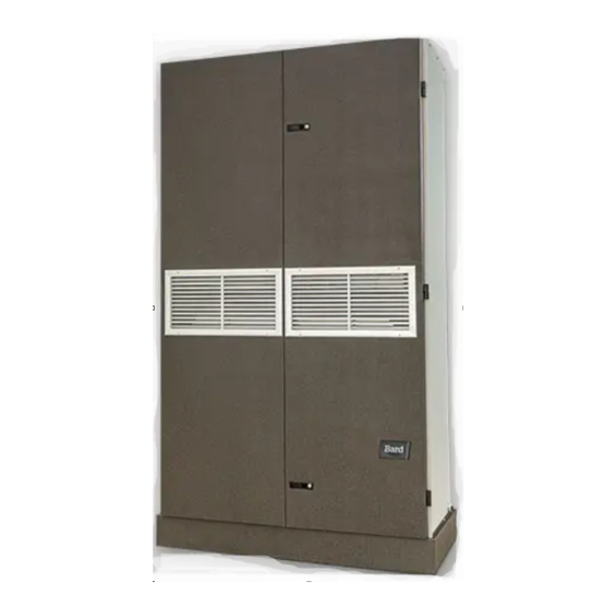
INSTALLATION INSTRUCTIONS
11EER Q-TEC
Q24H4-A
Q30H4-A
Q24H4-B
Q30H4-B
Q24H4-C
Q30H4-C
Q24H4DA
Q30H4DA
Q24H4DB
Q30H4DB
Q24H4DC
Q30H4DC
Packaged Heat Pump
Models:
Q36H4-A
Q36H4-B
Q36H4-C
Q36H4DA
Q36H4DB
Q36H4DC
Bard Manufacturing Company, Inc.
Bryan, Ohio 43506
www.bardhvac.com
QH Series
TM
Q43H4-A
Q43H4-B
Q43H4-C
Q43H4DA
Q43H4DB
Q43H4DC
Manual:
Supersedes: 2100-742A
Date:
Q48H4-A
Q48H4-B
Q48H4-C
Q48H4DA
Q48H4DB
Q48H4DC
2100-742B
11-10-20
Page
1 of 57
Advertisement
Table of Contents
Troubleshooting

Subscribe to Our Youtube Channel
Related Manuals for Bard Q-TEC QH Series


Summary of Contents for Bard Q-TEC QH Series
- Page 1 Q43H4-B Q48H4-B Q48H4-C Q24H4-C Q30H4-C Q36H4-C Q43H4-C Q24H4DA Q30H4DA Q36H4DA Q43H4DA Q48H4DA Q48H4DB Q24H4DB Q30H4DB Q36H4DB Q43H4DB Q48H4DC Q24H4DC Q30H4DC Q36H4DC Q43H4DC Bard Manufacturing Company, Inc. Manual: 2100-742B Bryan, Ohio 43506 Supersedes: 2100-742A Date: 11-10-20 www.bardhvac.com Page 1 of 57...
-
Page 2: Table Of Contents
CONTENTS Getting Other Information and Publications ..3 Service .................31 Solid State Heat Pump Control Troubleshooting Q-TEC General Information ........4 Procedure ............31 Q-TEC Model Nomenclature ........4 Checking Temperature Sensor Outside Unit Shipping Damage ..........4 Circuit..............32 Unit Removal from Skid .........4 Troubleshooting ECM 142R Outdoor Fan Motors ..33 Handling Unit after Removal from Skid ....6 Replacing the Motor ........34 General ..............6... -
Page 3: Getting Other Information And Publications
Table 16 Electronic Expansion Valve Figure 18C ............16 Troubleshooting ........47 Figure 18D ............17 Table 17 10K OHM NTC Sensor: Temperature/ Figure 19 Unit Dimensions ........19 Resistance ..........49 Figure 20 High Voltage Connections .......20 Table 18 Dehumidification Relay Logic Board ..56 Figure 21 Programmable Thermostat Connections ..24 Table 19... -
Page 4: Q-Tec Tm General Information
Q-TEC GENERAL INFORMATION Q-TEC Model Nomenclature – ACCESSORIES AND CONTROL MODEL SERIES OPTIONS X – Standard Controls CAPACITY E – Standard Controls, Low 24 – 2 Ton Ambient Control (LAC) 30 – 2½ Ton R – Standard Controls, LAC, 36 – 3 Ton Outdoor Thermostat (ODT) 43 –... -
Page 5: Figure 1 Air Seal Under Q-Tec Unit
FIGURE 1 Air Seal Under Q-TEC Unit Air Seal MIS-1008 FIGURE 2 Removal of Q-TEC Unit from Skid Hold Skid Down C Front Wheels On Floor A Shipping Brackets B Front Wheels Over Edge MIS-1007 Manual 2100-742B Page 5 of 57... -
Page 6: Handling Unit After Removal From Skid
Handling Unit after Removal from Skid FIGURE 4 Q-TEC Unit on Appliance Cart CAUTION Q/TEC UNIT Be careful pushing unit on rollers to prevent the unit from tipping over. Failure to do so could result in personal injury. The unit will have to be turned sideways and removed APPLIANCE CART from skid to fit through a doorway. -
Page 7: Minimum Installation Height
Minimum Installation Height The minimum installation height for ducted The minimum installation height of the unit with a free applications is 8' 4-1/2". This provides enough blow plenum is 8' 6". This provides enough clearance clearance to install the duct work (see Figure 6). for the plenum to be removed (see Figure 5). -
Page 8: Duct Work
Duct Work For hot water coil option, a QPBHW**-F for free blow or QPBHW**-D for ducted airflow is used. All duct work must be properly sized for the design When used with a ducted supply, a Q4CX Cabinet airflow requirement of the equipment. Air Conditioning Extension can be used to conceal the duct work above Contractors of America (ACCA) is an excellent guide to the unit to the ceiling. -
Page 9: Switching Filter Sizes
Switching Filter Sizes All capacity, efficiency and cost of operation information as required for Department of Energy To switch from 1" to 2" filters, remove the filter slide “Energyguide” Fact Sheets are based upon the fresh and bend the tabs down out of the way to accommodate air blank-off plate in place and is recommended for the 2"... -
Page 10: Commercial Room Ventilator (Option)
Commercial Room Ventilator (Option) Before starting, make sure the power has been turned off. The commercial room ventilator (CRV) can be seen after the main front doors are opened. The CRV must be removed to gain access to the mist eliminator. 1. -
Page 11: Installation
INSTALLATION Basic Installation Design and This unit is to be secured to the wall sleeve with mounting brackets provided. The unit itself, the supply Application Planning duct and the free blow plenum are suitable of “0” Successful unit installations require proper planning clearance to combustible material. -
Page 12: Figure 13A Unit Mounting - Method 1
FIGURE 13A Unit Mounting – Method 1 Side Trim (2 PCS.) Enlarged view of mounting bracket showing sleeve to cabinet attachment Side Trim (2 PCS.) Mounting Bracket Wall Sleeve #8 Screw Provided (Light Color) Mounting Bracket Cabinet Side Panel #10 Hex Head Screw Bottom Trim Provided... -
Page 13: Condensate Drain
FIGURE 14 floor or through the wall. If the drain is to be routed Remove Locking Screws from Wheels through an unconditioned space, it must be protected from freezing. The drain line must be able to be removed from the unit if it is necessary to remove the unit from the wall. -
Page 14: Optional Rear Drain Kits
FIGURE 17 Rear Drain (Top View) Drain Line Wall (maximum 10" for rear drain) Sleeve Couplings not shown but recommended for ease of removability for service Wall Bracket Water Trap Unit MIS-977 The drain box permanently mounts onto the wall sleeve Optional Rear Drain Kits and is then either piped directly outdoors, or can be Optional Rear Drain Kit Model QCDS48A is also... -
Page 15: Figure 18A
FIGURE 18A OVERFLOW TUBE CAULK AROUND TUBE WALL SLEEVE DRAIN BOX MIS-2469 FIGURE 18B PLUG INSTALLED IN SIDE Q/Tec DRAIN MIS-2469 REAR DRAIN CONNECTION IN Q/Tec PRODUCT IMPORTANT! 1/2" SLIP X 1/2" SLIP X 3/4" NPT TEE SUPPLIED WITH DRAIN BOX KIT 3/4"... -
Page 16: Figure 18C
FIGURE 18C REMOVE KNOCK-OUT FOR INDOOR DRAIN HOSE CONNECTOR (If used) MIS-2471 A Manual 2100-742B Page 16 of 57... -
Page 17: Figure 18D
FIGURE 18D DRAIN HOSE FROM INDOOR DRAIN PAN. MOVE HOSE FROM ATTACHMENT IN LOWER DRAIN PAN AND SLIDE ONTO DRAIN BOX BARB FITTING, SECURING WITH SUPPLIED CLAMP IF OUTDOOR PAN IS BYPASSED. ( WILL REDUCE RISK OF ALGAE GROWTH IN THE OUTDOOR PAN BUT AT A SLIGHT COOLING PERFORMANCE REDUCTION OF 2-3% ) MIS-2472 A... -
Page 18: Indoor Ducted And Non-Ducted Applications
The spacing between louvers on the grille directly in front of the unit return grilles and registers. shall not be larger than 5/8". Bard recommends at least 2' between solid objects and return grilles or registers. Thermostat or Indoor Temperature Sensor Placement... -
Page 19: Figure 19 Unit Dimensions
FIGURE 19 Unit Dimensions (Width) (Plenum Supply) (Returns) (Trim Width) Q24H4 Q30H4 5.000 42.000 30.000 (2) 17.000 43.000 Q36H4 Q43H4 3.000 48.000 40.000 (2) 20.000 49.000 Q48H4 All dimensions are in inches. Dimensional drawings are not to scale. TOP VIEW (SHOWN WITHOUT PLENUM) 5.000 SUPPLY AIR OPENING... -
Page 20: Wiring - Main Power
Wiring – Main Power The electrical data on the serial plate, in the unit specifications and also in Table 12 on page 41 list fuse Main electrical power must be supplied to the unit and wire sizes (75°C copper) for all models including from a clean, reliable power source. -
Page 21: Wiring - Low Voltage
Wiring – Low Voltage mode, the reduced airflow provides a warmer supply air temperature creating more comfortable heat. The All 230/208V 1 phase and 3 phase equipment have Y1 terminal is the 24VAC input for Balanced Climate dual primary voltage transformers. All equipment leaves compressor cooling operation. -
Page 22: Low Ambient Control
Low Ambient Control (LAC) The low ambient control is a pressure switch that is attached to the liquid line of the system and monitors high side system pressure. Operation of the LAC occurs as outdoor temperatures drop below 60ºF. LAC operation cycles the condenser fan on/off based on outdoor temperature. -
Page 23: Table 1 Wall Thermostats
TABLE 1 Wall Thermostats Part Number Predominate Features 8403-060 3 stage Cool; 3 stage Heat; Electronic Programmable/Non-Programmable; HP or Conventional; Auto or Manual (1120-445) changeover; Dehumidification Output 3 stage Cool, 3 stage Heat; Programmable/Non-Programmable; HP or Conventional; Auto or Manual Changeover; CS9B-THOA Humidity Sensor w/ dehumidification;... -
Page 24: Figure 21 Programmable Thermostat Connections
Programmable Thermostat Connections Completestat Model #CS9B-THOA or Model #CS9BE-THOA W1/E Thermostat W1/E YO/D Bard #8403-060 Optional CO2 Controller Bard Part #8403-067 24VAC CO2 OUT TEMP-OUT Unit Low B/W1 Voltage Term. Strip 12-Pin Vent Plug ALL VENT OPTIONS PLUG IN HERE If not equipped with a ventilation option to plug in, a jumper plug must be installed. -
Page 25: Figure 22 Non-Programmable Thermostat Connections
Non-Programmable Thermostat Connections Units With Dehumidification 8403-038 Mechanical Humidistat T4 Pro 8403-089 T6 Pro 8403-090 or 8403-092 8403-047 Electronic Humidistat Optional CO2 Controller Bard Part #8403-067 24VAC CO2 OUT TEMP-OUT Unit Low B/W1 Voltage Term. Strip 12-Pin Vent Plug ALL VENT OPTIONS PLUG IN HERE If not equipped with a ventilation option to plug in, a jumper plug must be installed. -
Page 26: Start Up
Exposure to high pressure refrigerant hazard. Topping Off System Charge Dehumidification models are equipped with an If a leak has occurred in the system, Bard electronic expansion valve (EEV). In order to fully Manufacturing recommends reclaiming, evacuating recover refrigerant or evacuate system during repairs,... -
Page 27: Three Phase Scroll Compressor Start Up
pressure switch settings: Opens 14 +/– 4 PSI, closes If phases are reversed, the red fault LED will be lit and 30 +/– 5 PSI. Refer to defrost control board for lockout compressor operation is inhibited. The phase monitor information. will also inhibit operation for an imbalance exceeding 12% at 208 VAC and 8% at 460 VAC. -
Page 28: Balanced Climate Tm Mode
Balanced Climate™ is a great comfort feature that can operations automatically. easily be applied under any normal circumstances. If the Bard air conditioning system is being set up If some abnormal or temporary condition such as a high in a typical environment where 72°F is the lowest... -
Page 29: Figure 23 Defrost Control Board
the timing circuit. This permits the defrost cycle to be There is also a 5-minute compressor time delay checked out in warmer weather conditions without the function built into the defrost control board. This is to outdoor temperature having to fall into the defrost region. protect the compressor from short cycling conditions. -
Page 30: Low Pressure Switch Bypass Operation
Low Pressure Switch Bypass Operation The control has a selectable (SW1) low pressure switch bypass set up to ignore the low pressure switch input during the first (30, 60, 120 or 180 seconds) of “Y” operation. After this period expires, the control will then monitor the low pressure switch input normally to make sure that the switch is closed during “Y”... -
Page 31: Service
SERVICE Solid State Heat Pump Control NOTE: If there was no power to 24 volt transformer, Troubleshooting Procedure the compressor and outdoor fan motor will not start for 5 minutes. This is because of the 1. NOTE: A thorough understanding of the defrost compressor short cycle protection. -
Page 32: Checking Temperature Sensor Outside Unit Circuit
Checking Temperature Sensor Outside 3. Check resistance reading to chart of resistance. Use sensor ambient temperature. (Tolerance of part Unit Circuit is ± 10%.) 1. Disconnect temperature sensor from board and 4. If sensor resistance reads very low, sensor is from outdoor coil. -
Page 33: Troubleshooting Ecm 142R Outdoor Fan Motors
Also ensure the motor is secure in its mounting system, and the mounting system is secure to the unit. The Bard Q-TEC is equipped with a low EXPOSED MOVING PARTS. ambient control pressure switch. This pressure... -
Page 34: Replacing The Motor
TABLE 7 Troubleshooting ECM™ 142R Outdoor Fan Motors Check between red and black wires for line power Check line power to motor Verify ground by checking green wire to L1 and L2 line power Check "BR" terminal of fan logic control board Check blue fan lead on fan relay terminal of defrost logic control ** Is not energized in cooling mode until low ambient fan cycling control is Check for 24VAC common signal to... -
Page 35: Troubleshooting Ecm Indoor Blower Motors
Troubleshooting ECM Indoor Blower Motors CAUTION: Symptom Cause/Procedure • Noisy blower or cabinet • Check for loose blower housing, panels, etc. Disconnect power from unit before removing or replacing • High static creating high blower speed? connectors, or servicing motor. To avoid electric shock - Check for air whistling through seams in from the motor’s capacitors, disconnect power and wait at ducts, cabinets or panels... -
Page 36: Replacing Ecm Control Module
Replacing ECM Control Module Verify that the replacement control is correct for the application. Refer to the manufacturer’s authorized To replace the control module for the GE variable-speed indoor blower replacement list. USING THE WRONG CONTROL WILL motor, take the following steps: RESULT IN IMPROPER OR NO BLOWER OPERATION. -
Page 37: Table 8 Troubleshooting Ecm Blower Motors
TABLE 8 Troubleshooting ECM Indoor Blower Motors Part Load Part Load Heat Pump Continuous Dehum. Heat Pump Cooling Heat Pump Full Full Load w/ Mode of Blower Full Load Mode Full Load w/ Emergency ("Y1-Y2" ("Y1-Y2" Load Heat 1st & 2nd Operation (Ventilation Cooling... -
Page 38: Fan Blade Setting Dimensions
Fan Blade Setting Dimensions R-410A Refrigerant Charge Shown in Figure 28 is the correct fan blade setting This unit was charged at the factory with the quantity of for proper air delivery across the outdoor coil. Refer to refrigerant listed on the serial plate. AHRI capacity and Table 9 for unit specific dimension. -
Page 39: Table 10A Cooling Pressure - Standard Airflow
TABLE 10A Cooling Pressure – Standard Airflow Air Temperature Entering Outdoor Coil °F Return Air Temp Model Pressure (DB/WB) Low Side 75/62 High Side Low Side Q24H4 80/67 High Side Low Side 85/72 High Side Low Side 75/62 High Side Low Side Q30H4 80/67... -
Page 40: Table 11 Cooling Pressure - Balanced Climate Airflow
TABLE 11 Cooling Pressure – Balanced Climate Airflow Air Temperature Entering Outdoor Coil °F Return Air Temp Model Pressure (DB/WB) Low Side 75/62 High Side Low Side Q24H4 80/67 High Side Low Side 85/72 High Side Low Side 75/62 High Side Low Side Q30H4 80/67... -
Page 41: Table 12 Electrical Specifications Q**H4 Series
TABLE 12 Electrical Specifications − Q**H4 Series Single Circuit Dual Circuit Maximum Rated No. Field Minimum Maximum Field External Field Power Ground Model Volts & Power Minimum Circuit External Power Ground Fuse or Wire Size Wire Size Phase... -
Page 42: Table 13 Indoor Blower Performance
TABLE 13 Indoor Blower Performance Balanced Climate Model Rated ESP* Maximum ESP* Vent* Rated CFM* CFM* Q24H4 0.10 Q30H4 0.10 Q36H4 0.15 1100 1125 Q43H4 0.15 1300 1300 Q48H4 0.20 1500 1500 1050 * These units are equipped with a variable speed (ECM) indoor motor that automatically adjusts itself to maintain approximately the same rate of indoor airflow in both heating and cooling, dry and wet coil conditions and at both 230/208 or 460 volts. - Page 43 GRAPH 1 Q24H4 FAD Ventilation Delivery GRAPH 2 Q30H4 FAD Ventilation Delivery Manual 2100-742B Page 43 of 57...
- Page 44 GRAPH 3 Q36H4 FAD Ventilation Delivery GRAPH 4 Q43H4 FAD Ventilation Delivery Manual 2100-742B Page 44 of 57...
- Page 45 GRAPH 5 Q48H4 FAD Ventilation Delivery Manual 2100-742B Page 45 of 57...
-
Page 46: Dehumidification Unit Instructions
DEHUMIDIFICATION UNIT INSTRUCTIONS Q**H4D dehumidification models provide a unique and control panel) need to be removed. Refer to unit dehumidification circuit for periods of low outdoor wiring diagram for clarity. ambient temperature and high indoor humidity This mode will allow the indoor blower to run at a conditions. -
Page 47: Troubleshooting The Electronic Expansion Valve
FIGURE 31 to be manually opened first. The valve can be opened High Side Connection manually using the magnetic EEV service tool (Bard Filter Drier P/N 2151-021) shown in Figure 30. To do this, remove FILTER DRIER... -
Page 48: Control Board
Check to see if valve can be moved by manually moving the stepper motor using the EEV service tool shown in Figure 30 (Bard Part # 2151-021). If valve still does not control, check the transducer and thermistor sensors as described on page 49. If sensors are good, replace the valve. -
Page 49: Thermistor Sensor
Thermistor Sensor 1. Make a visual check for broken wire insulation, 4. Compare the resistance reading to Table 17. Use broken wires or cracked epoxy material. sensor ambient temperature. (Tolerance of part is ±10 %.) 2. Disconnect 10k ohm NTC thermistor from the EEV control box. -
Page 50: Heat Pump Circuit Diagrams
INDOOR COIL EEV CONTROL Heat Pump Cooling Mode Circuit Diagram EEV TEMP 4-WAY VALVE REHEAT COIL SENSOR OUTDOOR COIL PRESSURE SENSOR CHECK VALVE DEHUMIDIFICATION VALVE COMPRESSOR MIS-3959 INDOOR COIL EEV CONTROL Heat Pump Dehumidification Mode Circuit Diagram EEV TEMP 4-WAY VALVE REHEAT COIL SENSOR OUTDOOR COIL... -
Page 51: Q24Hd Cooling And Dehumidification Application Data
Q24H4D Cooling and Dehumidification Application Data OD Temp. 75°F 85°F 95°F DB/WB Mode Dehum Dehum Dehum Total Cooling Btuh 25,100 10,000 23,500 6,300 21,600 1,900 Sensible Btuh 18,200 3,000 17,500 16,800 (2,600) 0.725 0.30 0.745 0.05 0.778 Latent Btuh 6,900 7,000 6,000 6,000... -
Page 52: Q30Hd Cooling And Dehumidification Application Data
Q30H4D Cooling and Dehumidification Application Data OD Temp. 75°F 85°F 95°F DB/WB Mode Dehum Dehum Dehum Total Cooling Btuh 29,700 11,900 28,100 7,900 26,600 4,100 Sensible Btuh 20,400 3,300 19,700 19,300 (2,800) 0.687 0.28 0.701 0.03 0.726 Latent Btuh 9,300 8,600 8,400 7,700... -
Page 53: Q36Hd Cooling And Dehumidification Application Data
Q36H4D Cooling and Dehumidification Application Data OD Temp. 75°F 85°F 95°F DB/WB Mode Dehum Dehum Dehum Total Cooling Btuh 34,800 14,800 32,700 11,000 31,200 6,500 Sensible Btuh 23,100 3,400 22,300 23,600 (3,300) 0.664 0.23 0.682 0.01 0.756 Latent Btuh 11,700 11,400 10,400 10,900... -
Page 54: Q43Hd Cooling And Dehumidification Application Data
Q43H4D Cooling and Dehumidification Application Data OD Temp. 75°F 85°F 95°F DB/WB Mode Dehum Dehum Dehum Total Cooling Btuh 42,600 16,800 40,200 11,400 37,700 5,600 Sensible Btuh 29,300 3,500 28,100 (600) 27,000 (4,800) 0.688 0.21 0.699 0.716 Latent Btuh 13,300 13,300 12,100 12,000... -
Page 55: Q48Hd Cooling And Dehumidification Application Data
Q48H4D Cooling and Dehumidification Application Data OD Temp. 75°F 85°F 95°F DB/WB Mode Dehum Dehum Dehum Total Cooling Btuh 48,900 18,500 46,200 12,600 43,400 6,400 Sensible Btuh 33,900 3,700 32,600 (700) 31,400 (5,000) 0.693 0.20 0.706 0.724 Latent Btuh 15,000 14,800 13,600 13,300... -
Page 56: Table 18 Dehumidification Relay Logic Board
TABLE 18 Dehumidification Relay Logic Board Energize on Occupied/ Unit Terminal Mode Inputs to the Board Outputs from the Board Unoccupied Strip Y1, G 1st Cooling Unoccupied Y1, G, A 1st Cooling Occupied 1st Cooling Y1, G, A, D Occupied w/Dehum ... -
Page 57: Table 19 Electrical Specifications Q**H4D Series
TABLE 19 Electrical Specifications – Q**H4D Series Single Circuit Dual Circuit Maximum Rated No. Field Minimum Maximum Field External Field Power Ground Model Volts & Power Minimum Circuit External Power Ground Fuse or Wire Size Wire Size Phase...
Need help?
Do you have a question about the Q-TEC QH Series and is the answer not in the manual?
Questions and answers