Advertisement
Quick Links
Installation Instructions
2x2 MiMo Omni-Directional Antenna
BS[G]M-6-60
SW3-963 - v1
1. Introduction
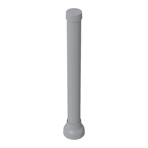
The BS[G]M-6-60 is a range of omni-directional tube antennas for 4G/5G applications requiring support for 2x2 MiMo with optional GPS/GNSS. Ideal for
fi xed site, marine or failover applications the antenna is suitable for external or internal mounting. The antenna is supplied with a wall mount bracket, with
brackets for mast or rail mounting and a sealing gasket for panel / deck mounting.
Electrical Safety Note
Variants of this product contain an active GPS/GNSS antenna. Rated voltage: 3-5VDC Rated current: 20mA maximum.
The supply to this device must be provided with overcurrent protection of 1A maximum.
2. Planning and Installation
To minimize the eff ects of surrounding objects, the antenna should be located as far away from other structures as possible. If fi tted with GPS/GNSS the
antenna should have a clear view of the sky. The orientation of the antenna should be vertical with the cable exiting downwards.
A bracket is supplied, allowing fi tment to a wall, rail or mast (18-50mm (3/4-2") diameter) using the u-bolts / clamps provided. The antenna bracket has
4x 8mm (5/16") clearance holes which also allow screw mounting. When mounting the antenna to a metal housing, device enclosure or mast care should
be taken to ensure that the antenna housing is elevated above the metal surface to which it is mounted. Ensure that the selected location will enable the
coaxial cable to be easily connected and routed to the equipment. If mounting the antenna using screws it is important to check for adequate under panel
clearance.
The antenna can also be mounted to fl at, level panels of up to 3mm (0.1") thickness using the supplied M6x1 screws and gasket. For thicker panels it may
be necessary to source longer M6x1 screws. The mounting panel can be conductive or non-conductive. Select a mounting location taking care to ensure
that there is at least 300mm (12") of clearance from proximate metal objects. Ensure that there is adequate clearance under the mounting panel and
measure to check for central positioning if necessary.
3. Safety Notes
• If the antenna will be fi tted to an existing mast, please ensure that it will not overload it.
• Ensure that the installation location can be safely accessed with the equipment that you have available.
• If mounting to a wall in a position which is accessible care should be taken to ensure that no one comes within 0.3m (1') of the antenna during use.
g
p
Parts of the antenna are an electrical conductor. Contact with power lines can result in death, or serious injury. Do not install the antenna where
there is any possibility of contact with (or high voltage arc-over from) power cables. The antenna and supporting mast must not be close to any
power lines during installation, removal or in the event that part of the system should accidentally fall.
If the antenna is installed above the roof line or in an exposed location, it is advisable to fi t lightning surge arrestors in the coaxial cable feed
lines. Suitable units should be sourced and installed as per the manufacturer instructions. The installer is responsible for determining if this is a
requirement for the antenna installation.
( )
g
Advertisement

Related Manuals for Panorama Antennas BSM-6-60


Summary of Contents for Panorama Antennas BSM-6-60
- Page 1 Installation Instructions 2x2 MiMo Omni-Directional Antenna BS[G]M-6-60 SW3-963 - v1 1. Introduction The BS[G]M-6-60 is a range of omni-directional tube antennas for 4G/5G applications requiring support for 2x2 MiMo with optional GPS/GNSS. Ideal for fi xed site, marine or failover applications the antenna is suitable for external or internal mounting. The antenna is supplied with a wall mount bracket, with brackets for mast or rail mounting and a sealing gasket for panel / deck mounting.
- Page 2 4. Mounting Using the Wall / Mast / Rail Bracket Check that you have the required mounting hardware and equip- ment available. The antenna can be bracket mounted via the supplied fi xing holes (suitable for machine screws or self-tapping screws) or rail / mast mounted using the supplied u-bolts / clamps.
- Page 3 6. Route Cables Route the coaxial cables to the radio equipment being careful not to foul any moving components. Respect a bend radius of 25mm (1”) for the cables if possible. Connect the antenna to the radio equipment. 7. Commission and Test Check GPS/GNSS cable (where applicable): ●...