Emerson CoreSense Application Engineering Bulletin
20 to 40 ton copeland scroll air conditioning compressors
Hide thumbs
Also See for CoreSense:
- Technical information (17 pages) ,
- Technical information (17 pages)
Table of Contents
Advertisement
AE8-1384 R6
Section
Safety
Safety Instructions. ...................................................... 2
Safety Icon Explanation. .............................................. 2
Shock, Fire, or Injury to Persons .................................. 3
Safety Statements. ...................................................... 3
Overview ...................................................................... 4
Features ...................................................................... 4
Application Usage ....................................................... 4
Part Numbers .............................................................. 4
Agency Recognition .................................................... 4
Product Specifications ................................................. 4
Mounting ...................................................................... 4
Terminal Description and Basic Field Wiring. .............. 4
Dielectric (Hipot) Testing .................................................. 5
Warning Codes ............................................................ 5
Alert/Lockout Codes .................................................... 5
Resetting Alert Codes ................................................. 6
© 2018 Emerson Climate Technologies, Inc.
CoreSense™ Communications for 20 to 40 Ton
Copeland Scroll™ Air Conditioning Compressors
TABLE OF CONTENTS
Page
Section
Communications .......................................................... 6
DIP Switch Configuration ............................................ 7
Jumper Setting. ........................................................... 7
PC Interface Software. ................................................. 7
Field Service ................................................................ 8
Troubleshooting ........................................................... 8
Tables
Module Part Numbers .................................................. 9
Module Specifications ................................................. 9
Accessory Parts .......................................................... 9
Modbus Map ......................................................... 10-12
DIP Switch Purpose ................................................... 13
LED Flash Code Information ................................ 13-14
Figures
Terminal Box Wiring Diagrams ................................... 15
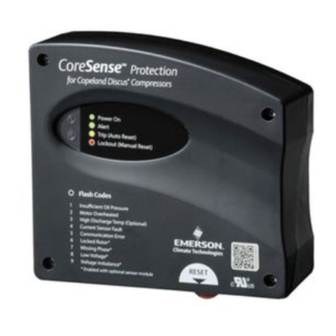
CoreSense™ Communications Module Photo. ......... 16
Thermistor Circuit Cable ............................................ 16
Modbus Addressing ................................................... 17
1
P
March 2018
Page
Advertisement
Table of Contents

Related Manuals for Emerson CoreSense


Summary of Contents for Emerson CoreSense
-
Page 1: Table Of Contents
AE8-1384 R6 March 2018 CoreSense™ Communications for 20 to 40 Ton Copeland Scroll™ Air Conditioning Compressors TABLE OF CONTENTS Section Page Section Page Safety Commissioning Safety Instructions............2 Communications ............6 Safety Icon Explanation..........2 DIP Switch Configuration ..........7 Instructions Pertaining to Risk of Electrical Jumper Setting. -
Page 2: Safety Instructions
AE8-1384 R6 Safety Instructions Copeland Scroll™ compressors with CoreSense™ Communications are manufactured according to the latest U.S. and European Safety Standards. Particular emphasis has been placed on the user’s safety. Safety icons are explained below and safety instructions applicable to the products in this bulletin are grouped on page 3. These instructions should be retained throughout the lifetime of the compressor. -
Page 3: Instructions Pertaining To Risk Of Electrical Shock, Fire, Or Injury To Persons
• Only qualified and authorized HVAC or refrigeration personnel are permitted to install, commission and maintain this equipment. • Electrical connections must be made by qualified electrical personnel. • All valid standards and codes for installing, servicing, and maintaining electrical and refrigeration equipment must be observed. © 2018 Emerson Climate Technologies, Inc. -
Page 4: Introduction
WARNING WARNING Terminal Description and Basic Field Wiring Figure 2 at the end of this bulletin shows the CoreSense CoreSense Communications modules are not Communications module. Figures 1a and 1b are the interchangeable with any other brand of motor terminal box wiring diagrams. -
Page 5: Dielectric (Hipot) Testing
5 minutes. PTC, NTC, and common connections. Once communication is reinitiated, the Warning will When multiple CoreSense Communications modules are be cleared. networked, a shielded, twisted pair cable such as Belden Code 2 - Reserved For Future Use #8761 (22 AWG) should be used for the communication wiring. -
Page 6: Resetting Alert Codes
Alert code will be exceeds the user configurable number of Code 4 cleared and CoreSense will allow normal operation. If the events within a 24 hour period. Once the module has fault is still present after the reset is performed the fault... -
Page 7: Dip Switch Configuration
“off”, the baud rate is 19200. If the switch is “on” the those listed in Table 4. baud rate is 9600. The baud rate of each CoreSense Communications module should be set to match the The history status messages give the order in which the master controller baud rate. -
Page 8: Service
SERVICE and NTC circuits simply remove the temperature plug from Field Service the CoreSense module and measure the resistance in the appropriate pins shown in Figure 3. The measured values Service compressors will be shipped with the CoreSense should be in the ranges listed in Table 2. For information... -
Page 9: Module Part Numbers
PRELIMINARY AEX-XXXX AE8-1384 R6 Table 1 CoreSense Communications Module Part Numbers Voltage OEM Part Number Service Part Number 571-0065-05 971-0065-04 120/240 571-0064-06 971-0064-05 Table 2 CoreSense Communications Module Specifications Module Part Number 571-0065-05 571-0064-06 120/240 VAC, 60HZ Module Voltage & Frequency... -
Page 10: Modbus Map
AEX-XXXX AE8-1384 R6 Table 4 - CoreSense Modbus Map NOTE:: Number of registers value to be send in the query = Number in the column “Message Length With Zero Stuffing” / 2 (e.g. number of reg required to read “Seven day Warning history with cumulative count” is 36 (72/2) - Page 11 PRELIMINARY AEX-XXXX AE8-1384 R6 Table 4 - CoreSense Modbus Map Continued Unused (18 bytes) - continued 0x0001 - PTC Status (OK-1/Not OK-0) 0x0002 - Scroll High Temp NTC Status (OK-1/Not OK-0) 0x0004 - Spare Temp NTC Status (OK-1/Not OK-0) 0x0008 - L1 Voltage Status (Present-1/Absent-0)
- Page 12 PRELIMINARY AEX-XXXX AE8-1384 R6 Table 4 - CoreSense Modbus Map Continued Parameters can be read using Function code 3 (Read Holding Register) Message Length in Message Length With Location in Hex Parameter Bytes Zero Stuffing Customer Id Code Customer Location...
-
Page 13: Dip Switch Purpose
PRELIMINARY AEX-XXXX AE8-1384 R6 Table 4 - CoreSense Modbus Map Continued Parameters can be write using Function code 16 (Preset Multiple Registers) Message Message Location in Length Parameter Length in Range Default With Zero Bytes Stuffing Customer Id Code Customer Location... - Page 14 Thermistor Configuration: TE* = PTC & NTC (3 wire connectors), TW* = PTC only (2 wire connectors) Table 6 - CoreSense™ Communications LED Flash Code Information The flash code number corresponds to the number of LED flashes, followed by a pause, and then the flash code is repeated.
-
Page 15: Terminal Box Wiring Diagrams
Module Low Low voltage on T2-T1 voltage is back in transformer Flash Code 9 Voltage terminals the normal range 3) Check for blown fuse in transformer secondary This Alert does not result in a Lockout © 2018 Emerson Climate Technologies, Inc. -
Page 16: Coresense™ Communications Module Photo
REGLAMENTARIA PARA EL PRODUCTO FINAL SHORT CYCLE PROTECTION / ENABLE / DISABLE / ACTIVADO DESACTIVADO - VEA LA PLACA DE DATOS PROTECCIÓN CONTRA CICLOS CORTOS 02-14 052-2895-00 Figure 1b - ZP236/296 Terminal Box Wiring Diagram © 2016 Emerson Climate Technologies, Inc. - Page 17 View A Motor PTC Thermistor Scroll NTC Thermistor (red wire) (black wire) Common Connection Spare Connection (blue wire) Terminal identification is from the end of the plug (View A) Figure 3 Thermistor Circuit Cable © 2016 Emerson Climate Technologies, Inc.
-
Page 18: Modbus Addressing
= 24 = 14 = 25 = 15 = 26 = 16 = 27 = 17 = 28 = 18 = 29 = 19 = 30 = 20 = 10 Figure 4 Modbus Addressing © 2016 Emerson Climate Technologies, Inc. - Page 19 Emerson Climate Technologies, Inc. reserves the right to modify the designs or specifications of such products at any time without notice. Emerson Climate Technologies, Inc. does not assume responsibility for the selection, use or maintenance of any product.
Need help?
Do you have a question about the CoreSense and is the answer not in the manual?
Questions and answers