
Related Manuals for Code Blue CB 4 Series


Summary of Contents for Code Blue CB 4 Series
- Page 1 CB 4 Series Installation | Confi guration | Operation | Troubleshooting Administrator Guide 800.205.7186 www.codeblue.com •...
- Page 2 OR OTHER INFORMATION CONTAINED HEREIN OR THE USE THEREOF. Code Blue Corporation reserves the right to make any modifications to this guide or the information contained herein at any time without notice. The software described herein may also be governed by the terms of a separate user license agreement.
-
Page 3: Table Of Contents
15 CB 4-s with Dual Faceplates Installation Instructions....26 16 CB 4-r Installation Instructions............28 17 CB 4-u Installation Instructions............30 18 CB 4 Series Remote Mount Beacon/Strobe Installation....33 19 S-1000/S-1050 Installation Instructions..........34 20 PoE Installation Instructions..............36 21 CB 4 Series Pole Mount Installation Instructions......37 22 CB 4 Series Curb Mount Installation Instructions...... - Page 4 CB 4 Series Administrator Guide 32 GSM Wireless Wiring Diagram (CB 4-u only)....... 49 33 Cellular Retro Instructions (CB 4-u only)........50 34 Solar and WindAssist Wiring Diagram (CB 4-u only)....55 35 NightCharge Wiring Diagram (CB 4-u only)........ 56 ®...
-
Page 5: Introduction
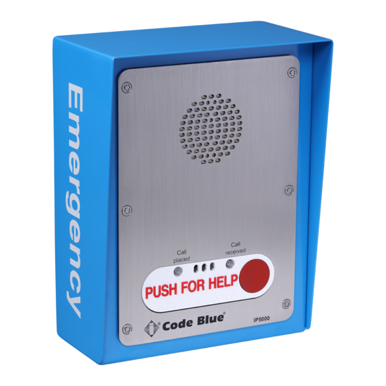
The all-steel housing and Code Blue’s speakerphone system meet the need for a highly vandal resistant unit, while providing a cost-effective and reliable solution. - Page 6 CB 4 Series Administrator Guide This guide contains all of the Code Blue CB 4 Series information for the CB 4-s, CB 4-u, and CB 4-r. This guide contains a general overview of the CB 4 Series options and its application, installation and wiring.
-
Page 7: Getting Started
1. EIA/TIA, ANSI, CSA and BICSI cabling or similar standards shall be adhered to for proper operation of Code Blue communication devices connected to copper or fiber infrastructures. Communications cable and electrical cable in the same conduit is not an acceptable instal- lation and shall not be supported. - Page 8 CB 4 Series Administrator Guide Tools Required CB 4-s and CB 4-r 1. Ladder to reach above unit – For Remote Beacon/Strobe Only 2. Drill and security bit for removing and inserting security screws on phone 3. 3/8 socket set to mount unit onto wall CB 4-u 1.
-
Page 9: Spare Parts
CB 4 Series Administrator Guide 4 Spare Parts CB 4-s Part Part Number Faceplate Screws 41544 (6pk) Power 4 Connector 24V 40109 Analog Surge Suppressor 41471 IP Surge Suppressor 41421 CB 4-s with Dual Faceplates Part Part Number Faceplate Screws... - Page 10 CB 4 Series Administrator Guide CB 4 Series Additional Options Part Part Number Solar Battery – CB 4-u only 41436 Solar Panel – CB 4-u only 40156 GSM Assembly – CB 4-u only - Solar only 40028 GSM Assembly – CB 4-u only – NightCharge...
-
Page 11: Power Requirements
CB 4 Series Administrator Guide 5 Power Requirements (2020) (The following power requirements include the 4 Series and also ALL OTHER Code Blue units.) Component Specs Faceplates Voltage Max Current Max Watts Norm Current Norm Watts KWHrs High V IA4100 24V AC 0.40... - Page 12 0.22 S-1050 LED Strobe w/ Photocell 24V AC 2.80 67.20 0.22 5.28 0.13 12V DC 2.68 32.16 0.38 4.56 0.11 CB 4 Series 24V DC 2.68 64.32 0.38 9.12 0.22 LED Light Bar 24V AC 0.04 0.96 0.04 0.96 0.02 12V DC 0.04...
- Page 13 ® CB 4-u w/ NightCharge 0.22 120V AC 0.13 0.11 CB 4 Series 0.22 0.02 0.01 0.02 Administrator Guide 1.21 Power Requirements continued Models With IP5000 Faceplate Voltage Current Watts KWHrs CB 1-e 24V AC 0.33 7.92 0.19 12V DC 0.43...
-
Page 14: Legacy Power Requirements
CB 4 Series Administrator Guide 6 Legacy Power Requirements (The following power requirements include the 4 Series and also ALL OTHER Code Blue units.) Code Blue 259 Hedcor Street Holland, MI 49423 USA 800.205.7186 www.codeblue.com page 14 of 65 GU-160-T •... - Page 15 CB 4 Series Administrator Guide Code Blue 259 Hedcor Street Holland, MI 49423 USA 800.205.7186 www.codeblue.com page 15 of 65 GU-160-T • • • •...
-
Page 16: Software Configuration
A sophisticated emergency management platform for your blue light phone network, ToolVox offers unique real-time monitoring and provisioning options for emergency phones and public address speakers, effectively acting as a hub for connecting Help Points and other Code Blue devices. Us- ® ing our proprietary incident response software, Blue Alert MNS and EMS, you can send alerts via ®... -
Page 17: Cb 4-S Low Voltage Exploded View
CB 4 Series Administrator Guide 8 CB 4-s Low Voltage Exploded View ITEM # DESCRIPTION Wall Mount Painted Assy Standard / Custom Graphic Grounding Lug 10-24 Nylock Nut Power 4 Connector 24V DISCLAIMER: Product design and component use subject to change without notice. Product shown reasonably represents current offering and is intended to assist in component identification. -
Page 18: Cb 4-R Low Voltage Exploded View
CB 4 Series Administrator Guide 9 CB 4-r Low Voltage Exploded View ITEM # DESCRIPTION Hooded Wall Mount Painted Assy Standard / Custom Graphic Faceplate Light Assy Grounding Lug 10-24 Nylock Nut Power 4 Connector 24V DISCLAIMER: Product design and component use subject to change without notice. Product shown reasonably represents current offering and is intended to assist in component identification. -
Page 19: Cb 4-S With Dual Faceplates Low Voltage Exploded View
CB 4 Series Administrator Guide 10 CB 4-s with Dual Faceplates Low Voltage Exploded View ITEM # DESCRIPTION Hooded Wall Mount Dual Painted Assy Standard / Custom Graphic Grounding Lug 10-24 Nylock Nut Power 4 Connector 24V DISCLAIMER: Product design and component use subject to change without notice. Product shown reasonably represents current offering and is intended to assist in component identification. -
Page 20: Cb 4-U Low Voltage Exploded View
CB 4 Series Administrator Guide 11 CB 4-u Low Voltage Exploded View BALL # PART # DESCRIPTION BALL # PART # DESCRIPTION CALL Standard / Custom Graphic 50101 Single Button IP5000 VoIP Phone – PUSH FOR HELP 41471 Analog Surge Suppressor 50102 Double Button IP5000 VoIP Phone –... -
Page 21: Cb 4-U High Voltage Exploded View
CB 4 Series Administrator Guide 12 CB 4-u High Voltage Exploded View BALL # PART # DESCRIPTION BALL # PART # DESCRIPTION CALL Standard / Custom Graphic 50101 Single Button IP5000 VoIP Phone – PUSH FOR HELP 41471 Analog Surge Suppressor 50102 Double Button IP5000 VoIP Phone –... -
Page 22: How To Replace Led Light Connectors
Administrator Guide 13 How to Replace LED Light Connectors As of 2020, Code Blue strobe, area and faceplate lights come with Wago connectors. These con- nectors provide ease of use and a much stronger connection. Below are the steps needed to change to the new connectors. - Page 23 CB 4 Series Administrator Guide Strip all wires and twist tight. Place small screwdriver into square hole and push down. Insert cut wire into round hole and remove screwdriver. Repeat on the rest of the connectors. Once all connectors have been switched, you are ready to apply power to the LED.
-
Page 24: Cb 4-S Installation Instructions
CB 4 Series Administrator Guide 14 CB 4-s Installation Instructions 1.0 PRE-INSTALLATION 1.1 Electrical preparation – The unit may have supply wires run from either A) behind the unit through the wall, or B) below the unit using an external conduit through the bottom of the unit’s back plate. - Page 25 CB 4 Series Administrator Guide 1 3/16 MOUNTING SURFACE 4 9/16 REF Ø7/8 THRU BOTTOM PLATE BOTTOM PLATE (KNOCKOUT FOR Ø1/2 CONDUIT) 5 1/8 REF 2 7/8 10 1/4 REF Ø7/8 4 X Ø7/16 MOUNTING HOLES (KNOCKOUT FOR Ø1/2 CONDUIT)
-
Page 26: Cb 4-S With Dual Faceplates Installation Instructions
CB 4 Series Administrator Guide 15 CB 4-s with Dual Faceplates Installation Instructions 1.0 PRE-INSTALLATION 1.1 Electrical preparation – The unit may have supply wires run from either A) behind the unit through the wall, or B) below the unit using an external conduit through the bottom of the unit’s back plate. - Page 27 CB 4 Series Administrator Guide 1 3/16 MOUNTING SURFACE 4 9/16 REF Ø7/8 THRU BOTTOM PLATE BOTTOM PLATE (KNOCKOUT FOR Ø1/2 CONDUIT) 5 1/8 REF 2 7/8 4 X Ø7/16 MOUNTING HOLES Ø7/8 (KNOCKOUT FOR Ø1/2 CONDUIT) 4 1/16 25 3/4 REF...
-
Page 28: Cb 4-R Installation Instructions
CB 4 Series Administrator Guide 16 CB 4-r Installation Instructions 1.0 PRE-INSTALLATION 1.1 Electrical preparation – The unit may have supply wires run from either A) behind the unit through the wall, or B) below the unit using an external conduit through the bottom of the unit. - Page 29 CB 4 Series Administrator Guide 1 3/16 MOUNTING SURFACE 4 9/16 REF Ø7/8 THRU BOTTOM PLATE BOTTOM PLATE (KNOCKOUT FOR Ø1/2 CONDUIT) 5 1/8 REF 2 7/8 10 1/4 REF Ø7/8 4 X Ø7/16 MOUNTING HOLES (KNOCKOUT FOR Ø1/2 CONDUIT)
-
Page 30: Cb 4-U Installation Instructions
CB 4 Series Administrator Guide 17 CB 4-u Installation Instructions PRE-INSTALLATION 1.1 Electrical preparation – The unit may have supply wires run from either (a) behind the unit through the wall, or (b) below the unit using an external conduit through the bottom of the unit’s back plate. - Page 31 CB 4 Series Administrator Guide Code Blue 259 Hedcor Street Holland, MI 49423 USA 800.205.7186 www.codeblue.com page 31 of 65 GU-160-T • • • •...
- Page 32 CB 4 Series Administrator Guide 14 REF 1 5/8 REF MOUNTING SURFACE 1 5/8 8 7/8 REF BOTTOM PLATE Ø1-1/8 THRU BOTTOM PLATE (KNOCKOUT FOR 3/4 CONDUIT) Ø1-1/8 THRU TOP PLATE 2 1/2 (KNOCKOUT FOR Ø3/4 CONDUIT) 2 7/8 4 X Ø9/16 MOUNTING HOLES...
-
Page 33: Cb 4 Series Remote Mount Beacon/Strobe Installation
CB 4 Series Administrator Guide 18 CB 4 Series Remote Mount Beacon/Strobe Installation ATTACH J-BOX TO THE POLE Thread the banding (B) through the pole bracket (A) located on the backside of the J-box (C). Wrap the banding around the pole. Cut the banding to desired length. -
Page 34: 1000/S-1050 Installation Instructions
CB 4 Series Administrator Guide 19 S-1000/S-1050 Installation Instructions NOTE: Instructions pertain to Model S-1000 LED Beacon/Strobe and Model S-1050 LED Beacon/Strobe only POSITIVE (12-24V DC or AC) BLACK COMMON (GROUND) YELLOW (FLASH MODE) DRY CONTACT CLOSED = "ON" YELLOW... - Page 35 CB 4 Series Administrator Guide PROGRAMMING PRIMARY & SECONDARY MODES 1. Remove power from unit. 2. Short the Yellow wires together. 3. Restore power to the unit and wait until the unit begins to flash. Once the unit begins to flash, remove the short.
-
Page 36: Poe Installation Instructions
12V DC switch position favors the DATA – PoE+ side of the module First: Electrical connections, All 4 Customer Code Blue devices should to be Cat5e connected to the 5 place manifold DATA DATA – PoE+ Second: Manifold fused red lead... -
Page 37: Cb 4 Series Pole Mount Installation Instructions
CB 4 Series Administrator Guide 21 CB 4 Series Pole Mount Installation Instructions 1.0 THREAD MOUNTING STRAPS THROUGH SLOTS – Use outside slots for larger poles and inside slots for smaller poles. 2.0 HOLD BRACKET TO POLE – Set the height of the bracket (C) so that the speakerphone push button(s) on the unit will be at desired height (please check with local codes for ADA compliance). -
Page 38: Cb 4 Series Curb Mount Installation Instructions
16 inches of wire coming out of the top of the curb mount to connect to the Code Blue phone. A 7/8 inch conduit hole in the back of the unit has been provided. 2.0 INSTALLATION PROCEDURES – Curb Mounts should be mounted on concrete bases with a minimum depth of 4 inches, using the correct mounting bolts for your application. - Page 39 CB 4 Series Administrator Guide Code Blue 259 Hedcor Street Holland, MI 49423 USA 800.205.7186 www.codeblue.com page 39 of 65 GU-160-T • • • •...
-
Page 40: Cb 4-U Solar Installation Instructions
CB 4 Series Administrator Guide 23 CB 4-u Solar Installation Instructions INSTALL THE SOLAR PANEL 1.1 Attach the pole mount bracket – See pole mount installation instructions. The bracket must point due south. 1.2 Attach the solar panel – The solar panel assembly mounts to the pole mount bracket using a stainless steel sheet metal solar bracket. -
Page 41: Cb 4 Series 24V Standard Wiring
CB 4 Series Administrator Guide Incoming Low Voltage 24 CB 4 Series 24V Wiring (2020) 12 -24V AC or DC Faceplate LED Bar (If Applicable) Remote Beacon Strobe (If Applicable) 0.5 Amp Fuse 0.5 Amp Fuse IA4100 Phone Line In... -
Page 42: Cb 4 Series Poe Wiring
CB 4 Series Administrator Guide 25 CB 4 Series PoE Wiring (2020) Incoming POE Power Faceplate LED Bar (If Applicable) Remote Beacon Strobe (If Applicable) 0.5 Amp Fuse 0.5 Amp Fuse IP5000 To Ground Patch Cable Incoming POE Product wiring diagram shown reasonably represents current offering and is intended to assist in component identifi cation and service. Earlier product production may have different components and wiring connections. -
Page 43: Cb 4 Series 24V Standard Wiring
CB 4 Series Administrator Guide 26 CB 4 Series 24V Wiring (2015-2020) ⼀ ⴀ ⴀ Product wiring diagram shown reasonably represents current offering and is intended to assist in component identifi cation and service. Earlier product production may have different components and wiring connections. Reference the model and serial number from the unit ID tag and contact manufacturer to confi rm replacement part version and availability. -
Page 44: (Prior To 2015)
CB 4 Series Administrator Guide 27 CB 4 Series 24V Wiring (prior to 2015) ⼀ ⴀ ⴀ Product wiring diagram shown reasonably represents current offering and is intended to assist in component identifi cation and service. Earlier product production may have different components and wiring connections. Reference the model and serial number from the unit ID tag and contact manufacturer to confi rm replacement part version and availability. -
Page 45: (Prior To 2015)
CB 4 Series Administrator Guide 28 CB 4-u Series 24V or 120V Multi-Tap Power Brick Wiring (prior to 2015) Product wiring diagram shown reasonably represents current offering and is intended to assist in component identifi cation and service. Earlier product production may have different components and wiring connections. -
Page 46: (After 2015) (With 24V Fuse Block)
CB 4 Series Administrator Guide 29 CB 4-u Series 24V Standard Wiring (after 2015) (with Fuse Block) Lighting Units IA4100 LED Area Light Beacon Strobe 24 Volts AC / DC or 12 – 24 Volts AC or DC 12VDC Output CB1 s&d... -
Page 47: (Prior To 3/2013) (With Hammond Transformer)
CB 4 Series Administrator Guide 30 CB 4-u Series 120V Standard Wiring (prior to 03/2013) (with Hammond Transformer) Product wiring diagram shown reasonably represents current offering and is intended to assist in component identifi cation and service. Earlier product production may have different components and wiring connections. Reference the model and serial number from the unit ID tag and contact manufacturer to confi rm replacement part version and availability. - Page 48 CB 4 Series Administrator Guide 31 CB 4-u Series 120V Standard Wiring (after 2015) (with Triad Transformer) Lighting Units Beacon Strobe 12 – 24 Volts AC or DC IA4100 LED Faceplate light 12 – 24 Volts AC or DC Output...
-
Page 49: Gsm Wireless Wiring Diagram (Cb 4-U Only)
CB 4 Series Administrator Guide 32 GSM Wireless Wiring Diagram (CB 4-u only) ® I R E L E S S NOT SUPPLIED BY ® ® Product wiring diagram shown reasonably represents current offering and is intended to assist in component identifi cation and service. Earlier product production may have different components and wiring connections. -
Page 50: Cellular Retro Instructions (Cb 4-U Only)
CB 4 Series Administrator Guide 33 Cellular Retro Instructions (CB 4-u only) TELULAR SX-5E & CALLFINDER CX100FX2 GSM-4 TO GSM-5 Installation Instructions Retrofit Instructions Telular & CallFinder We strongly advise reading these instructions before any work is started. In addition, the actual wir- ing may have changed by others, therefore the wiring guides provided are originals and here for your reference. - Page 51 Remove Code Blue phone, 6 screws, then tilt the top of the faceplate outward and lift out. l Disconnect (unplug) all connections, and set phone aside. d. Locate the CallFinder. It’s behind the phone and up. You should be able to see all three connections.
- Page 52 CB 4 Series Administrator Guide GSM-5 Installing the GSM-5 1. Before mounting the GSM-5 box, open the box by removing the four screws on the power input side of the GSM-5. You can slide out the tray and insert the SIM card into the SIM card holder.
- Page 53 CB 4 Series Administrator Guide GSM-5 LED Indicator Readout External Interfaces - Front Panel Received Signal Strength Indicator A stack of four green LEDs on the left side of the front panel indicate the relative signal strength of the cellular radio signal. It is analogous to the ‘bars’ display on a cellular telephone handset.
- Page 54 CB 4 Series Administrator Guide Cellular (yellow) LED LED STATUS CELLULAR RADIO Not registered - or - Call active Blinking 1sec on + 2 sec off Registered in idle * When the CELLULAR LED stays on (not registered) for more than a few minutes after powering the POTSwap, it is usually an indication of a poor antenna connection or a problem with the activation on the cellular network.
-
Page 55: Solar And Windassist Wiring Diagram (Cb 4-U Only)
CB 4 Series Administrator Guide 34 Solar WindAssist™ Wiring Diagram (CB 4-u only) (Solar) (NightCharge ® Product wiring diagram shown reasonably represents current offering and is intended to assist in component identifi cation and service. Earlier product Product wiring diagram shown reasonably represents current offering and is intended to assist in component identifi cation and service. Earlier product production may have different components and wiring connections. -
Page 56: Nightcharge® Wiring Diagram (Cb 4-U Only)
CB 4 Series Administrator Guide 35 NightCharge® Wiring Diagram (CB 4-u only) Product wiring diagram shown reasonably represents current offering and is intended to assist in component identifi cation and service. Earlier product production may have different components and wiring connections. Reference the model and serial number from the unit ID tag and contact manufacturer to confi rm replacement part version and availability. -
Page 57: Wm-180 Wall Mount Installation Instructions
IP Controller board. Reference IA4100 Admin and User Guide for programming of analog controller board. Reference IP5000 Admin and User Guide for programming of IP controller board. Code Blue Guides are located at www.codeblue.com > support > downloads. WITHOUT CONTROLLER BOARD... - Page 58 CB 4 Series Administrator Guide Product wiring diagram shown reasonably represents current offering and is intended to assist in component identifi cation and service. Earlier product production may have different components and wiring connections. Reference the model and serial number from the unit ID tag and contact manufacturer to confi rm replacement part version and availability.
- Page 59 CB 4 Series Administrator Guide 2.50 10.00 15.00 3.50 MTG HOLES 8.50 1.13 CONDUIT HOLE 4.05 2.05 7.50 BACK VIEW 20.10 15.12 10.40 Specifications subject to change without notice or obligation 1.13 CONDUIT HOLE on the part of the manufacturer.
-
Page 60: Wm-180 Pole Mount Installation Instructions
CB 4 Series Administrator Guide 37 WM-180 Pole Mount Installation Instructions 1.0 THREAD MOUNTING STRAPS THROUGH SLOTS 2.0 HOLD BRACKET TO POLE – Set the bracket at the desired height for the Public Address Speak- ers 180°. 3.0 BAND THE BRACKET TO THE POLE AT DESIRED HEIGHT 3.1 To eliminate waste, pull band (A) from carton as needed. -
Page 61: Maintenance Schedule
CB 4 Series Administrator Guide 38 Maintenance Schedule LEGEND Guard tasks Technician tasks DAILY OR WEEKLY Perform functional communications check Action: Press red button Strobe activates Red LED “Call Placed” light turns on Message plays Call connects, green LED “Call Received” light turns on ... - Page 62 Administrator Guide UNIT SURFACE MAINTENANCE The painted and stainless steel Code Blue models require periodic care to sustain their aesthetic appearance. Units located outdoors are vulnerable to harsh environmental conditions, including UV rays, acid rain, diesel fumes and airborn iron particles (i.e., dust) which over time may cause unit discoloring.
-
Page 63: Locating Unit Serial Numbers
CB 4 Series Administrator Guide 39 Locating Unit Serial Numbers CB 4-s CB 4-r SERIAL NUMBER LOCATION CB 4-s with CB 4-u Dual Faceplates Code Blue 259 Hedcor Street Holland, MI 49423 USA 800.205.7186 www.codeblue.com page 63 of 65 GU-160-T •... -
Page 64: Warranty
Administrator Guide 40 Warranty Code Blue Corporation provides a limited warranty on this product. Refer to your sales agreement to establish the terms. In addition, Code Blue’s standard warranty language, as well as information regarding support for this product while under warranty, is available at www.codeblue.com/support. -
Page 65: Download Information
CB 4 Series Administrator Guide Download Information 41 Download Information Code Blue now has a centralized location where you can find installation, setup, information, configuration and operation instructions. ® 1. Centry Administrator Guide: www.codeblue.com/resources/guides 2. CB 1 Series Administrator Guide: www.codeblue.com/resources/guides...
Need help?
Do you have a question about the CB 4 Series and is the answer not in the manual?
Questions and answers