
Related Manuals for Command Light KNIGHT 2


Summary of Contents for Command Light KNIGHT 2
- Page 1 Effective March 2020 This guide supersedes all previous versions MODEL COVERED: KL409D 3842 Redman Drive 1-800-797-7974 Fort Collins, CO 80524 www.CommandLight.com...
- Page 2 KNIGHT THANK YOU Please allow us to express a simple thank you for investing in a COMMAND LIGHT product. As a company, we are dedicated to producing the very best and most versatile flood lighting package available. We take great pride in the quality of our work and hope that you will find many years of satisfaction from the use of this equipment.
- Page 3 USER GUIDE...
-
Page 4: Table Of Contents
KNIGHT Please take the time to read this manual before installing or operating the COMMAND LIGHT KNIGHT Save this guide for future reference. Contents Breakage or Damage During Shipment ............................6 Product Safety Precautions ................................7 General Description and Specifications ............................7 Operation ...................................... - Page 5 COMMAND LIGHT at the above address indicating the model number, serial number and type of defect. No parts or equipment will be received by COMMAND LIGHT for repair or replacement under this warranty without specific written authority from it in advance.
-
Page 6: Breakage Or Damage During Shipment
KNIGHT Warranty/Service COMMAND LIGHT products* come with a industry leading 5 year warranty against any defects in materials and workmanship when used and operated for a period of five years. If during this time period, you have any malfunctions not related to misuse, accident, neglect, or normal wear and tear, please take the following steps in order to have your light tower serviced under COMMAND LIGHT’s warranty. -
Page 7: Product Safety Precautions
Do not use a COMMAND LIGHT KNIGHT that has been damaged or is not fully functional, including non-working indicator lamps. Never hold any part of the COMMAND LIGHT KNIGHT with a hand or foot while it is in motion. The COMMAND LIGHT KNIGHT has numerous pinch points. -
Page 8: General Description And Specifications
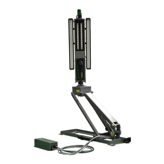
KNIGHT General Description and Specifications The KNIGHT is designed to provide high intensity emergency scene lighting with quick precision. As with any electromechanical device, take precautionary steps to ensure safe operation. Never operate the KNIGHT near overhead power lines. There are several standard lighting options available for the KNIGHT Model # Description Minimum Power Requirements... -
Page 9: Raising The Light From The Nested Position
USER GUIDE Operation Raising the light from the nested position Using the control box, raise the lower or upper stage. You may also activate both stages simultaneously. Control switches are of momentary action style and must be held in the “on”... -
Page 10: Returning The Light To The Nested Position
KNIGHT Returning the light to the nested position The KNIGHT is equipped with an Autopark function as a standard feature. The green button on the control box initiates the Autopark sequence. Once initiated, the “Emergency Stop” red button indicator is illuminated. Pressing the “Emergency Stop” button will cancel the Autopark sequence. -
Page 11: Tools Required
64” 64” Hole punch for metal with and 1 diameter capacity 8” 16” Phillips head screwdriver, #2 Command Light flat blade screwdriver (included with light) combination wrenches and/or ratchet and sockets 16” 2” 16” 2” 8” adjustable wrench Tongue and Groove Pliers... -
Page 12: Location Requirements
KNIGHT Location Requirements Model 409D can be mounted on any location that is 50” x 13”. The The standard KNIGHT surface should be flat or have only a slight crown. For a recessed installation allow for a minimum of 60” x 20”. Consult with factory before construction of recessed installation. Verify all dimensions before installation to ensure proper operation of light will not infringe on other installed components. -
Page 13: Mounting
USER GUIDE Mounting Place the provided spacers in the location of the light mounting holes. The spacers may be modified to conform to the contour of the mounting location. Remove any obstructions below the mounting surface such as headliners. Attach any necessary lifting attachments to the KNIGHT . -
Page 14: Electrical Wiring
KNIGHT Electrical Wiring Please Note: Detailed internal wiring schematics are located at the back of this user guide. Run the control wire from the control box holster to the KNIGHT Run the power wire from the breaker box or generator to the KNIGHT . -
Page 15: Warning Device Wiring
USER GUIDE Warning Device Wiring Tools Required: • 3/32” Flathead Screwdriver • Wire Strippers • Small Torch or Lighter Wire the gray 22-20 control cable wires to the small connectors using the wiring schematics provided. There are 2 different schematics, one is the standard version and the other is the version for dual control with wireless controllers or V-Mux control. -
Page 16: Kl409D (Kl Slim) Relay Box Wiring
KNIGHT KL409D (KL Slim) Relay Box Wiring Tools Required: • 1/8” Flathead Screwdriver • #2 Phillips Screwdriver • Wire Strippers • 7/16” Nut driver or Wrench • Wire Crimpers • Large Cable Crimpers • Bosch Crimpers • 15/16”, 1 1/16”, 1 5/8” Wrenches or Channel Locks •... - Page 17 USER GUIDE Wire the 10 Awg blue/white and green wires to the middle pole strip in the relaybox. Also wire the smaller cable into the middle pole strip in the relaybox. Order: 1. 10 Awg Blue/White 2. 10 Awg Green 3.
-
Page 18: Maintenance
13. If it is still hitting off center, repeat previous steps. 14. If problems adjusting center still persist you may need to adjust the center switch bracket, or call Command Light at 1-800-797-7974 for further assistance. -
Page 19: Rotation Belt Adjustment
• Having the lamp tree at either extreme of fully up or down, will affect the degree of centering. Setting center while the lamp tree at a 45 degree angle produces the best results. If problems persist, please call Command Light at 1-800-797-7974. Rotation Belt Adjustment 1. -
Page 20: Power Failure
KNIGHT Power Failure The KNIGHT can be retracted manually if power to the unit is lost. If power loss is temporary, reestablishing power may be easier than manually retracting the light. Note: Disconnect power source from the KNIGHT before manual operation. Rotate to center Locate the belly plate on the bottom of the lift arm and remove it by loosening all 4 screws and only removing 2 of them. -
Page 21: Retract The Upper Stage
USER GUIDE Note the upper stage of the light weighs in excess of 100 pounds, use caution. Apply upward pressure on the main lift arm to remove support blocking then slowly lower the lift arm allowing the actuator shaft to extend past the lower pivot blocks. Retract the upper stage. -
Page 22: Troubleshooting
KNIGHT Troubleshooting Problem Possible Cause Solution Unit will not extend No power to the unit Check power input connections. Incorrect installation Refer to installation instructions. Upper stage will not Lower stage not raised above Raise lower stage higher. rotate safety limit (16” above base) Rotation motor failure. - Page 23 USER GUIDE...
-
Page 24: Technical Specifications - Standard Dc Models (409D-H4)
KNIGHT Technical Specifications – Standard DC Models (409D-H4) Dimensions (with strobe and ½” mounting spacers) – May vary by model: Height(Depth) Length Width Retracted 12” 51” 13” Extended 88” 54” 13” Recessed installation 14” 60” 20” Minimum Weight: 190 pounds Wiring: 50’... -
Page 25: Specifications
USER GUIDE Specifications... -
Page 26: Parts Lists
KNIGHT Exploded View (Lower Stage) -
Page 27: Exploded View (Lower Stage)
USER GUIDE Parts List (Lower Stage) -
Page 28: Exploded View (Midplate)
KNIGHT Exploded View (Midplate) - Page 29 USER GUIDE...
-
Page 30: Exploded View (Lamp Tree)
KNIGHT Exploded View (Lamp Tree) - Page 31 USER GUIDE...
- Page 32 KNIGHT Exploded View (Relay Box)
- Page 33 USER GUIDE Parts List (Relay Box)
-
Page 34: Wiring Schematics
KNIGHT Wiring Schematics... -
Page 35: Holster Box
USER GUIDE Holster Box... - Page 36 KNIGHT...
- Page 37 USER GUIDE...
-
Page 38: Midplate
KNIGHT Midplate... -
Page 39: Lamp Tree
USER GUIDE Lamp Tree...
Need help?
Do you have a question about the KNIGHT 2 and is the answer not in the manual?
Questions and answers