
Related Manuals for Command Light CL802A


Summary of Contents for Command Light CL802A
- Page 1 CL SERIES Effective August 2021 This guide supersedes all previous versions MODEL COVERED: 3842 Redman Drive 1-800-797-7974 CL802A Fort Collins, CO 80524 www.CommandLight.com...
- Page 3 COMMAND LIGHT THANK YOU Please allow us to express a simple thank you for investing in a COMMAND LIGHT product. As a company, we are dedicated to producing the very best and most versatile flood lighting package available. We take great pride in the quality of our work and hope that you will find many years of satisfaction from the use of this equipment.
- Page 4 USER GUIDE...
-
Page 5: Table Of Contents
COMMAND LIGHT Read this manual before installing or operating the COMMAND LIGHT. Save this guide for future reference. Contents Warranty ..............................4 Breakage or Damage During Shipment ....................5 Product Safety Precautions ........................6 General Description and Specifications ....................7 Operation .............................. -
Page 6: Warranty
Hourly rates for service are to be determined at the time of authorization by COMMAND LIGHT, travel time is paid at a maximum of 50% of the authorized service rate. -
Page 7: Breakage Or Damage During Shipment
COMMAND LIGHT 6. Finally, we will pay by mailing a check or crediting the account of the person, department, or company doing the repair. Payments will not be made until all requested parts have been returned. Please contact us as soon as problems arise in order to execute our warranty. We must have knowledge of the issue and provide a work authorization in order to pay or reimburse labor or travel time. -
Page 8: Product Safety Precautions
[ Do not use a COMMAND LIGHT that has been damaged or is not fully functional, including non-working indicator lamps. [ Never hold any part of the COMMAND LIGHT with a hand or foot while it is in motion. [ The COMMAND LIGHT has numerous pinch points. Keep loose clothing,... -
Page 9: General Description And Specifications
The umbilical corded control unit is powered via 12 VDC eliminating hazardous voltage levels within the hand held control box. The COMMAND LIGHT is manufactured to provide years of service with a minimum of maintenance. -
Page 10: Operation
Control switches are of momentary action style and must be held in the “on” position to actuate the stages. The COMMAND LIGHT has an override system that precludes rotation of the upper stage until the lower stage has elevated approximately 16" from the nested position. When the lower stage is below 16"... -
Page 11: Returning The Light To The Nested Position
COMMAND LIGHT Returning the light to the nested position The COMMAND LIGHT is equipped with an Autopark function as a standard feature. The “P” button on the control box initiates the Autopark sequence. Once initiated, the “Emergency Stop” button indicator is illuminated. Pressing the “Emergency Stop”... -
Page 12: Installation
When routing the connecting electrical wires take care to avoid sharp bends, hot components or other hazards to the wire. The COMMAND LIGHT is not designed to be operated in a raised position while the vehicle is in • motion. The COMMAND LIGHT includes warning circuit wiring to enable a warning device. -
Page 13: Location Requirements
COMMAND LIGHT Location Requirements The standard COMMAND LIGHT CL802A model can be mounted on any location that is 73" x 36". The surface should be flat or have only a slight crown. For a recessed installation allow for a minimum of 86"... -
Page 14: Mounting
Control Box Holster Mounting Using the holster as a template, mark hole locations. Drill 17/64" mounting holes. Drill any holes required to route the control wire from the control box to the COMMAND LIGHT unit. Mount holster box with provided hardware. -
Page 15: Electrical Wiring
Run the control wire from the control box holster to the COMMAND LIGHT. Run the power wire from the breaker box or generator to the COMMAND LIGHT. A 40 Amp breaker is recommended on AC models. -
Page 16: Warning Device Installation
USER GUIDE Warning Device Installation Tools Required: • " Flathead Screwdriver • Wire Strippers • Small Torch or Lighter Wire the gray 22-20 control cable wires to the small connectors using the wiring schematics provided on pages 41 and 42. There are 2 different schematics, one is the standard version and the other is the version for dual control with wireless controllers or V-Mux control. -
Page 17: Maintenance
Maintenance Cleaning The COMMAND LIGHT is constructed with corrosion resistant aluminum and stainless steel fasteners. To further enhance corrosion resistance all exposed surfaces receive a powder coated paint finish. To assure years of trouble free service periodically clean all external surfaces with a mild detergent solution and a gentle spray of water. -
Page 18: Rotation Belt Adjustment
USER GUIDE 5. Follow the two motor wires down to the pole strip and disconnect. Brown wire (negative) red/white wire (Positive). Note: The same wires that come off the old motor will be the same wires you use for the new rotation motor. Swap the wires from the old motor to the new motor. -
Page 19: Center Switch Adjustment
12. If it is still hitting off center, repeat steps 3-11. If problems adjusting center still persist you may need to adjust the height on the set screw, or call Command Light at 1-800-797-7974 to order a new switch part number 065-12884. -
Page 20: Power Failure
USER GUIDE Power Failure The COMMAND LIGHT can be retracted manually if power to the unit is lost. If power loss is temporary, reestablishing power may be easier than manually retracting the light. Note: Disconnect power source from the COMMAND LIGHT before manual operation. -
Page 21: Troubleshooting
COMMAND LIGHT Troubleshooting Problem Possible Cause Solution Unit will not extend No power to the unit Check power input connections. Refer to installation instructions. Incorrect installation Upper stage will not rotate Lower stage not raised above Raise lower stage higher. -
Page 22: Holster Circuit Board Error Codes
USER GUIDE... -
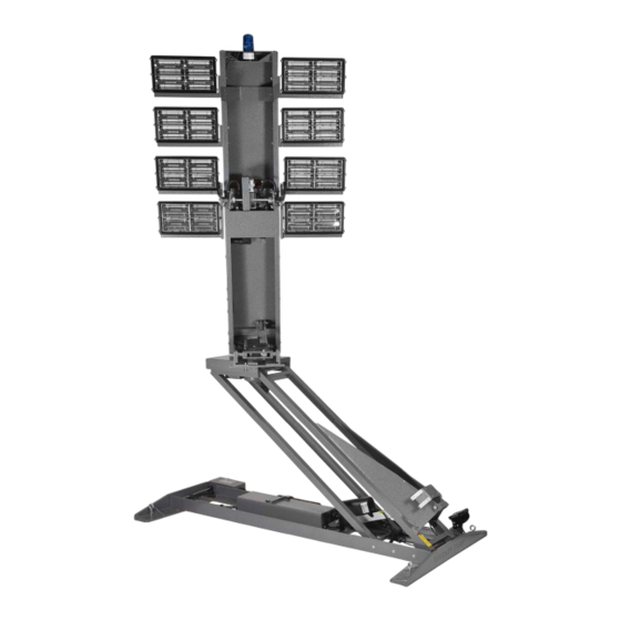
Page 23: Technical Specifications - Standard Ac Models (802A)
COMMAND LIGHT Technical Specifications – Standard AC Models (CL802A) Dimensions (with strobe and ½” mounting spacers) Height(Depth) Length Width Retracted 12.75" 74" 41" Extended 10'-7" 80" 41" Recessed installation 12.75" 86" 48" Minimum Weight: 306 pounds Wiring: Main Power VAC... -
Page 24: Specifications
USER GUIDE Specifications... -
Page 25: Parts Lists - Exploded Views
COMMAND LIGHT EXPLODED VIEWS AND WIRING SCHEMATICS... - Page 26 USER GUIDE Parts List - Lower Stage A...
-
Page 27: Exploded View (Lower Stage A)
COMMAND LIGHT Exploded View - Lower Stage A... - Page 28 USER GUIDE Parts List - Lower Stage B...
-
Page 29: Exploded View (Lower Stage B)
COMMAND LIGHT Exploded View - Lower Stage B... - Page 30 USER GUIDE Parts List - Upper Stage A...
-
Page 31: Exploded View (Upper Stage A)
COMMAND LIGHT Exploded View - Upper Stage A... - Page 32 USER GUIDE Parts List - Upper Stage B...
-
Page 33: Exploded View (Upper Stage B)
COMMAND LIGHT Exploded View - Upper Stage B... - Page 34 USER GUIDE Parts List - Lamp Tree...
-
Page 35: Exploded View (Lamp Tree)
COMMAND LIGHT Exploded View - Lamp Tree... -
Page 36: Relay Box
USER GUIDE Parts List - Relay Box... - Page 37 COMMAND LIGHT Exploded View - Relay Box...
- Page 38 USER GUIDE...
-
Page 39: Entrance Box
COMMAND LIGHT Parts List/Exploded View - Entrance Box... -
Page 40: Wiring Schematics
USER GUIDE Wiring Schematics... - Page 41 COMMAND LIGHT...
- Page 42 USER GUIDE...
-
Page 43: Holster Box
COMMAND LIGHT Holster Box... - Page 44 USER GUIDE Holster Box...
-
Page 45: Ops Wireless Controller (Vmux/Wireless Systems)
COMMAND LIGHT STANDARD STATION A TO CONTROLLER CHASSIS GROUND 12V IGNITION LIGHT TOWER STATION B TO VMUX WIRELESS CONTROL SPLITTER BOARD... -
Page 46: Lamp Tree (Strobe, Backlight)
USER GUIDE Lamp Tree (Strobe) - Page 47 COMMAND LIGHT Lamp Tree (Backlight)
-
Page 48: Midplate
USER GUIDE... -
Page 49: Relay Box
COMMAND LIGHT...
Need help?
Do you have a question about the CL802A and is the answer not in the manual?
Questions and answers