Epiroc EC Series Safety And Operating Instructions Manual
Hydraulic breakers
Hide thumbs
Also See for EC Series:
- Safety and operating instructions manual (28 pages) ,
- Safety and operating instructions manual (76 pages)

Related Manuals for Epiroc EC Series


Summary of Contents for Epiroc EC Series
- Page 1 90T, 100T, 120T, 135T Safety and operating instructions Hydraulic breakers © Construction Tools GmbH | 33905145 01 | 2019-09-11 Original Instructions...
-
Page 3: Table Of Contents
Contents Table of Contents 1 Introduction .......................... 6 About these Safety and Operating Instructions.................... 6 2 Safety instructions........................ 7 Signal words................................ 7 Qualification ................................ 8 Intended use ................................ 8 Use other than intended ............................. 8 Protective equipment............................ 9 Carrier, precautions ............................ 9 Transport, precautions ............................ 9 Hydraulic installation, precautions ......................... 10 Special parts, precautions .......................... 10 2.9.1 Piston accumulator ............................ 10... - Page 4 Contents 5.1.3 Grease................................ 20 5.1.4 Gas .................................. 20 Manufacturing the adapter plate........................ 21 Installing the adapter plate.......................... 21 Attaching the hydraulic attachment to the carrier .................. 22 5.4.1 Mechanical mounting aspects ......................... 22 5.4.2 Making the hydraulic connections ........................ 22 Removing the hydraulic attachment from the carrier.................. 24 5.5.1 Dismantling the hydraulic connections ......................
- Page 5 Contents Checking the working tool .......................... 41 Checking the wear bush EC 90T........................ 42 7.10 Checking the wear bushes and impact ring EC 100T, EC 120T, EC 135T ........... 43 7.11 Piston accumulator............................ 44 7.11.1 Checking the pressure in the piston accumulator.................... 45 7.11.2 Release the pressure from the piston accumulator .................. 45 7.11.3 Filling / topping up the piston accumulator ......................
-
Page 6: Introduction
1.1 About these Safety and 1 Introduction Operating Instructions Epiroc is a leading productivity partner for the mining, in- frastructure and natural resources industries. With cut- The aim of these Instructions is to familiarise you with ting-edge technology, Epiroc develops and produces in-... -
Page 7: Safety Instructions
Safety and operating instructions 2.1 Signal words 2 Safety instructions The signal words Danger, Warning, Caution, and Notice This is the safety alert symbol. It is used to alert are used as follows in these Safety and operating in- you to potential personal injury hazards. Obey structions: all safety messages that follow this symbol to avoid possible injury or death. -
Page 8: Qualification
Safety and operating instructions 2.2 Qualification 2.3 Intended use Transporting the hydraulic attachment is only permitted Only attach the hydraulic breaker to a hydraulic carrier of if carried out by people who: a suitable load-bearing capacity. • are authorised to operate a crane or a forklift truck Only use the hydraulic breaker function of the device to according to the applicable national provisions, break or fragment concrete, stone and rocks. -
Page 9: Protective Equipment
Safety and operating instructions 2.5 Protective equipment 2.7 Transport, precautions Personal protective equipment must comply with the ap- WARNING Risk of death due to suspended loads plicable health and safety regulations. When lifting loads these can swing out and fall. This can n Do not work wearing jewelry or with loose long hair. -
Page 10: Hydraulic Installation, Precautions
Safety and operating instructions 2.8 Hydraulic installation, 2.9 Special parts, precautions precautions 2.9.1 Piston accumulator WARNING Hydraulic pressure too high DANGER Danger of explosions If the hydraulic pressure is too high, the parts of the hy- draulic attachment will be exposed to excessively high The integrated piston accumulator is filled with nitrogen loads. -
Page 11: Media/Consumables, Precautions
Safety and operating instructions 2.10 Media/consumables, 2.11 Explosion and fire, precautions precautions WARNING Hot hydraulic oil under high pressure DANGER Explosion and fire Hydraulic oil will squirt out under high pressure if there is Explosions cause serious injury or death. If the working a leakage. -
Page 12: Electrical Shock, Precautions
Safety and operating instructions 2.12 Electrical shock, precautions 2.14 Emissions, precautions DANGER Electrical shock WARNING Noise hazard Any contact of the hydraulic attachment with electric cir- Operating the hydraulic attachment creates a loud noise. cuits or other sources of electricity will lead to an electric Long term high sound pressure level can affect your shock, resulting in serious injury or death. -
Page 13: Repair, Precautions
Never carry out any changes to the hydraulic attach- ment or the adapter plate. u Only use original parts or accessories approved by Epiroc. u Modifications that entail new hazards may require a new procedure for assessing conformity. © Construction Tools GmbH | 33905145 01 | 2019-09-11... -
Page 14: Overview
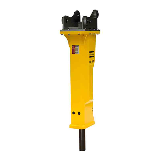
Safety and operating instructions 3.2 Function 3 Overview The operation of a hydraulic breaker is described in a greatly simplified version below: 3.1 Equipment description The pressure line »P« supplies oil at the operating pres- The illustration gives an overview of the main parts and sure of the carrier to the hydraulic breaker. -
Page 15: Signs / Labels
Safety and operating instructions 3.3.2 Labels 3.3 Signs / labels Sound Power WARNING Missing warnings The label states the guaranteed The name plate and the labels on the hydraulic attach- sound power level in accordance ment contain important information about the hydraulic with EC directive 2000/14/EC. -
Page 16: Applications
Demolition Heavily reinforced con- crete, demolition of power n Check the delivery for visual damage. stations and bridges n If any defects are found, consult the Epiroc Customer Rock mining/breaking Primary breaking Center / dealer in your area. Secondary breaking,... -
Page 17: Transport
Safety and operating instructions 4 Transport WARNING Hoist tipping over / hydraulic attach- ment falling The hydraulic attachment is heavy. The hoist/lifting equipment and/or hydraulic attachment tipping over or falling may cause serious injury and material damage. u Only transport the hydraulic attachment with lifting ●... -
Page 18: Transport Using A Crane
Safety and operating instructions 4.1 Transport using a crane 4.2 Transport using a forklift truck n Secure the hydraulic attachment with ropes or chains as shown in the following illustration. WARNING Hydraulic attachment tipping over The hydraulic attachment tipping off the fork of the forklift truck or the pallet may cause serious injury. -
Page 19: Transport Using A Truck
Safety and operating instructions 4.3 Transport using a truck WARNING Hydraulic attachment tipping over / slipping The hydraulic attachment slipping or tipping over and falling from the loading area of a lorry may cause serious injury. u Place the hydraulic attachment on a pallet. u Strap the hydraulic attachment to the pallet using suitable strapping (see illustration in chapter Trans- port using a forklift truck). -
Page 20: Installation
Dispose of it in accordance with the applicable envi- Our hydraulic attachments are basically designed for use ronmental regulations. with mineral oils. Consult the Epiroc Customer Center / Dealer in your area before using other hydraulic oils ap- 5.1 Media/consumables proved by the carrier manufacturer. -
Page 21: Manufacturing The Adapter Plate
Safety and operating instructions 5.2 Manufacturing the adapter WARNING Hands and fingers being cut off or hurt Bores and surfaces can act like a pair of scissors and plate cut off or hurt parts of your body. Construction Tools GmbH also supplies base plates to u Never use your fingers to check bores or fitting sur- manufacture adapter plates alternatively to the adapter faces. -
Page 22: Attaching The Hydraulic Attachment To The Carrier
The adapter plate must not be stopped by mechanical cut off or hurt parts of your body. stops in either position. Consult the Epiroc Customer u Never use your fingers to check bores or fitting sur- Center/Dealer in your area if the adapter plate is stopped faces. - Page 23 Safety and operating instructions n Check that the ports and connections on the hy- NOTICE Total damage to the hydraulic attachment draulic breaker and/or on the hydraulic hoses are not Polluted hydraulic lines and connections may enable damaged. sand, fragments of material and dirt to penetrate the hy- draulic attachment and damage it completely.
-
Page 24: Removing The Hydraulic Attachment From The Carrier
Safety and operating instructions 5.5 Removing the hydraulic WARNING Injury by impacts A sudden movement of the carrier may cause your as- attachment from the carrier sistant to be hit and injured by the boom or the hydraulic n Place the hydraulic attachment on timber support attachment. -
Page 25: Working Tool
Safety and operating instructions 5.7.1 Selecting the right working tool 5.7 Working tool The standard available working tools are shown. The dif- WARNING Unexpected movement ferent cutter geometries may influence the production re- Sudden movements of the carrier may cause serious in- sult, depending on the actual use. -
Page 26: Installation
Safety and operating instructions NOTICE Damage to percussion piston and working 5.7.2 Installation tool n Place the hydraulic breaker on timber support blocks. The percussion piston hits the working tool at high speed. If there is grease between the percussion pis- NOTICE The working tool may break ton and the working tool it can result in serious dam- There is an increased risk of the working tool breaking if... -
Page 27: Removal
Safety and operating instructions 5.7.3 Removal n Place the hydraulic breaker on timber support blocks. WARNING The working tool suddenly comes loose A clamped working tool is still under the pressure of the piston accumulator. When the working tool is loosened, it will partly jump out of the hydraulic breaker;... -
Page 28: Operation
Safety and operating instructions 6.1 Initial operation and operation 6 Operation after long storage WARNING Hot hydraulic oil squirting out Prior to first use and after more than eight weeks storage The hydraulic system is under high pressure. If hydraulic of the hydraulic breaker, the pressure in the piston accu- connections come loose, hydraulic oil will squirt out un- mulator must be checked. -
Page 29: Preparations Before Starting
/ or the the hydraulic attachment may be flung away and can Epiroc Customer Center / Dealer in your area. cause serious injury if people are hit by them. Small ob- jects falling from a great height can also cause serious n Switch the hydraulic attachment on and off, as de- damage. -
Page 30: Correct Operation
Safety and operating instructions Larger swing angles would lead to bending loads and 6.5 Correct operation damage to the working tool and the hydraulic breaker. 6.5.1 Working angle n Always position the tool so that it hits the material to 6.5.2 Advance be broken at a right angle. -
Page 31: Low Ambient Temperature
Safety and operating instructions n Start the hydraulic attachment when the temperature In summer and in tropical climates, the minimum re- quirement is a hydraulic oil of type HLP 68. has risen to 0 °C (32 °F). n During operations, leave the carrier engine and pumps running even during breaks. -
Page 32: Moving Objects
Safety and operating instructions 6.6.3 Moving objects 6.6.5 Blank firing of the working tool The working tool "blank fires" if the percussion energy is n Never use the hydraulic attachment to move debris. transferred to the retainer bars instead of to the material This would damage the hydraulic attachment. -
Page 33: Cylinder End Positions
Safety and operating instructions 6.6.7 Cylinder end positions n Avoid operating the hydraulic attachment when the carrier stick and bucket cylinder is in one of its end positions. These end positions have damping facilities; the hy- draulic cylinder may be damaged by prolonged use while in its end positions. -
Page 34: Maintenance
Safety and operating instructions 7 Maintenance WARNING Unexpected movement Sudden movements of the carrier may cause serious in- The maintenance activities are carried out by the carrier jury. driver. u Secure the carrier such that it cannot move unex- pectedly. WARNING Hot hydraulic oil squirting out u Observe the carrier manufacturer’s instructions. -
Page 35: Maintenance Schedule
Safety and operating instructions 7.1 Maintenance schedule during a shift Check the lubricant film on the shaft of the working tool approx. every 2 hours. Manual lubrication of the working tool approx. every 2 hours. daily Check the bolted connections at the adapter plate and tighten as required. Check the hydraulic lines for leaks. -
Page 36: Depressurising The Hydraulic System
Safety and operating instructions Case 2: If no facility for measuring the pressure is 7.2 Depressurising the hydraulic present in the supply pipe to the hydraulic breaker and system the return pipe is connected to the tank without an inter- mediate valve connection, you must observe the follow- Even when you have switched off the carrier, a consider- ing steps in order to depressurise the hydraulic breaker:... -
Page 37: Cleaning
Safety and operating instructions the shut-off valves or disconnect the quick-release 7.4 Lubrication couplings, so that no hydraulic oil can flow back from the carrier. 7.4.1 Checking the lubricant film The lubricant film on the shaft of the working tool must 7.3 Cleaning be checked during the work shift. -
Page 38: Manual Lubrication For Hydraulic Breakers Without Contilube® Ii
If you have questions how to use the ContiLube ® II, n Remove the plug from the breaker box. contact the Epiroc Customer Center / dealer in your area. n Put the manual grease gun on the grease nipple and inject chisel paste. -
Page 39: Contilube® Ii Operation
Safety and operating instructions 7.4.5 ContiLube® II operation 7.4.6 Manual lubrication Please remember the following: Manual lubrication is required if the automatic lubrication ® system fails to work. • The ContiLube II (C) is self-venting, i.e. the system does not require you to vent it. n Place the hydraulic breaker at a right angle on the •... -
Page 40: Chisel Paste Filling Device
3363 0664 11 find any signs of wear, such as sharp edges, notches or severe erosion. For further information, please contact the Epiroc Cus- tomer Center / Dealer in your area. n Deburr the retainer bars and bolts by careful grinding. -
Page 41: Checking The Percussion Piston Impact Surface
Check the impact surface of the working tool for chips found the surface to be chipped or cracked. and cracks. n Consult the Epiroc Customer Center / Dealer in your n Check the impact surface of the working tool for de- area. -
Page 42: Checking The Wear Bush Ec 90T
100 operating hours. The wear bush can be replaced on site. Consult the Epiroc Customer Center / Dealer in your area. n Remove all remnants of lubricant from the inside of the lower breaker part before installing new parts. -
Page 43: Checking The Wear Bushes And Impact Ring Ec 100T, Ec 120T, Ec 135T
Clean the area around the impact ring to enable a visual check. Replacing the wear bushes is only permitted if carried out by professionals trained by Epiroc. Consult the Epiroc Customer Center / Dealer in your area. n Remove all remnants of lubricant from the inside of the main body before installing new parts. -
Page 44: Piston Accumulator
Safety and operating instructions 7.11 Piston accumulator The pressure in the piston accumulator is measured at the filling valve (G). The piston accumulator is also filled through this valve. A. impact ring B. upper wear bush C. lower wear bush n Replace the lower wear bush when its inside diame- ter has reached the maximum permissible diameter. -
Page 45: Checking The Pressure In The Piston Accumulator
Safety and operating instructions 7.11.1 Checking the pressure in the piston 7.11.2 Release the pressure from the accumulator piston accumulator Check the gas pressure in the piston accumulator n Release gas from the piston accumulator to depres- monthly, and in cases of decreasing power or failure of surise the piston accumulator or if the value mea- the hydraulic breaker. -
Page 46: Checking The Hydraulic Lines
Safety and operating instructions n Close the pressure relief valve (D). 7.12 Checking the hydraulic lines n Connect the filling hose end (H) to the minimess con- n Before starting your work shift, always carry out a vis- nection (C) of the pressure relief valve (D). ual check of all lines (pipes and hoses) from the pump to the hydraulic attachment and from there to n Open the valve of the nitrogen bottle (F). -
Page 47: Bolt Connections / Tightening Torques
Safety and operating instructions 7.16 Bolt connections / Tightening torques The bolt connections of hydraulic breakers are subjected to very high loads. Tighten any loose connections without exceeding the recommended tightening torques. EC 90T EC 100T Connection point Interval Type of spanner Size / Torque Adapter plate* (fastening screws) A daily... - Page 48 Safety and operating instructions © Construction Tools GmbH | 33905145 01 | 2019-09-11 Original Instructions...
- Page 49 Safety and operating instructions EC 120T EC 135T Connection point Interval Type of spanner Size / Torque Adapter plate* (fastening screws) A daily Allen key 22 mm (0.87 in.) / 1500 Nm (1106 ft lbs) Ports »P« and »T« B weekly open-ended 50 mm (1.97 in.) / 275 Nm (203 ft lbs) wrench Cover for control mechanism / C in case of a re-...
- Page 50 Safety and operating instructions © Construction Tools GmbH | 33905145 01 | 2019-09-11 Original Instructions...
-
Page 51: Troubleshooting
Replace the magnet Workshop Operating pressure too low Check the carrier engine speed, the Carrier driver or Epiroc Customer pump delivery and the pressure relief Center / Dealer in your area valve; check the operating pressure Adjust settings and replace defective parts if required 8.2 Hydraulic breaker operates too slowly... -
Page 52: Impact Force Too Low
(see chapter Technical specifications) Return pressure too high Check and lower the return pressure Epiroc Customer Center / Dealer in your area Hydraulic oil return to the tank via a Connect the hydraulic oil return circuit Carrier driver or Epiroc Customer... -
Page 53: Oil Leaks From Ports "P" Und "T
Safety and operating instructions 8.5 Oil leaks from ports »P« und »T« Cause Remedy Cap nuts loose Check the cap nuts and tighten (see Carrier driver chapter Bolt connections/Tighten- ing torques) Hose connection CL to port »P« for Check the cap nuts and tighten Carrier driver ®... -
Page 54: Operating Temperature Too High
Check carrier settings and adjust Epiroc Customer Center / Dealer in your area Operation in high outside temperature Check oil temperature and install an Workshop or Epiroc Customer Cen-... -
Page 55: Repair
Construction Tools GmbH. These professionals must follow all safety instructions and guidelines for repair. n For technical support contact the Epiroc Customer Center / Dealer in your area. 9.1 Sending in the hydraulic attachment for repairs... -
Page 56: Storage
Safety and operating instructions 10.2 Working tool 10 Storage n Grease the working tool with chisel paste to prevent it WARNING Hydraulic breaker / working tool fall from corroding. The hydraulic breaker and the working tool are heavy. If n Store the working tool in a dry, properly ventilated they topple over or fall down from where they are stored, room. -
Page 57: Disposal
Safety and operating instructions 11.2 Hydraulic hoses 11 Disposal n Drain the hydraulic oil from the hydraulic hoses and NOTICE Environmental damage due to consumables collect it. Hydraulic oil and chisel paste are environmentally harm- ful and must not penetrate the ground or enter the water n Dispose of the hydraulic hoses in accordance with table or water supplies. -
Page 58: Technical Specifications
AutoStop AutoStop AutoStop Weights apply to standard carriers only. Any variances must be agreed with Epiroc and/or the carrier manufacturer prior to attachment. Hydraulic breaker incl. breaker box, working tool, and adapter plate of medium size. Please note that the service weight can be considerably higher, depending on the adapter plate. -
Page 59: Noise Declaration Statement
Safety and operating instructions 12.1 Noise declaration statement EC 90T EC 100T EC 120T EC 135T Sound pressure 88 dB(A) 88 dB(A) 92 dB(A) 93 dB(A) Sound power 116 dB(A) 118 dB(A) 120 dB(A) 122 dB(A) Sound pressure level according to EN ISO 3744 in accordance with Directive 2000/14/EC at 10 metres distance. Guaranteed sound power according to EN ISO 3744 in accordance with Directive 2000/14/EC inclusive spread in pro- duction. -
Page 60: Ec Declaration Of Conformity (Ec Directive 2006/42/Ec)
Safety and operating instructions 13 EC Declaration of Conformity (EC Directive 2006/42/EC) We, Construction Tools GmbH, hereby declare that the machines listed below conform to the provisions of EC Directive 2006/42/EC (Machinery Directive) and 2000/14/EC, ANNEX V (Noise Directive), and the harmonised standards men- tioned below. - Page 64 Any unauthorized use or copying of the contents or any part thereof is prohibited. This applies in particular to trademarks, model denominations, part numbers, and drawings. epiroc.com...
Need help?
Do you have a question about the EC Series and is the answer not in the manual?
Questions and answers