Table of Contents
Advertisement
Quick Links
Advertisement
Table of Contents

Subscribe to Our Youtube Channel
Related Manuals for Epiroc FlexiROC T20 R


Summary of Contents for Epiroc FlexiROC T20 R
- Page 1 Epiroc FlexiROC T20 R Operator's instructions PM No. 9852 2467 01i...
- Page 2 Only use genuine Epiroc parts. © Copyright 2017, Epiroc Stonetec S.r.l. Any unauthorized use or copying of the contents or any part thereof is prohibited. This applies in particular to trademarks, model denominations, part numbers and drawings.
- Page 3 Safety Safety Reference ………………………………………………………………………………………………………5...
- Page 4 Safety...
- Page 5 Safety Reference Note Always read the information in the Safety document before starting to use the rig or starting maintenance work.
- Page 6 afety...
-
Page 7: Table Of Contents
Hydraulic pump 2 ......................17 Hydraulic pump 3 ......................17 Hydraulic pump 4 ......................17 Air system ..........................17 2.Technical data ..........................18 FlexiROC T20 R ........................18 Dimensions ..........................20 Dimensions ........................... 20 Transport dimensions ......................20 Coverage area ........................21 Danger zone ........................ - Page 8 Touch buttons ........................... 47 Menu views ........................... 48 Navigation ......................... 48 Menu description ....................... 49 Menus for testing ....................... 51 Error messages ........................53 Function ..........................56 Time-out function ......................56 Start-up ..........................56 Stops ..........................57 Drilling ..........................57 Display heater........................
- Page 9 8. Drilling ............................. 84 Start of manual drilling......................84 Feeder adjustment during drilling ..................86 Checks during drilling ....................... 87 Break loose ........................... 87 Break loose (applies to extension drilling) ................87 Rod adding ..........................88 Threading ..........................90 Unthreading and extracting ....................... 91 Changing drill bit ........................
-
Page 11: General
See separate instructions for documentation on the rock drill/rotation unit, the diesel engine and certain other components. For other questions refer to the local Epiroc company office. Addresses and tel- ephone numbers are in the Maintenance instructions. -
Page 12: Principal Components
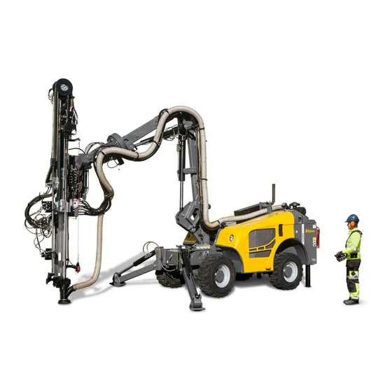
Operator's instructions 1. General Principal components Figure: Principal components Feeder Dust collector (DCT) Boom system Compressor Radiator Radio receiver Hydraulic oil pumps Wheels Diesel engine Electric cabinet Air tank... -
Page 13: General System Description
Operator's instructions 1. General General system description General description of the drill rig This drill rig is a fully diesel-hydraulic drill rig designed for surface drilling applications such as in quarries and on construction sites. The drill rig consists of the following main components: (See illustration under General Description). - Page 14 Operator's instructions 1. General Wheeled chassis frame The diesel engine, chassis, dust collector, hydraulic system, air system and boom sys- tem are mounted on the wagon frame. The 4 wheels are driven by two steering axles with integrated brake. The body covers the diesel engine, the compressor, the different lubrication tanks, the valves and the hydraulic hoses.
- Page 15 Operator's instructions 1. General The emergency stop buttons/cables are connected in series with the diesel engine cut- out system. As soon as an emergency stop button/cable is activated, the diesel engine will be stopped immediately. Reset the emergency stop buttons before restarting the engine.
- Page 16 Operator's instructions 1. General Steering Impact Lubrication pump Feed Drill rotation Stability Jacks Oil cooler Feed swing Pump 4 Feed dump Diesel engine Feed extension Pump 1 Roll over Pump 2 Drill steel support Pump 3 Hydraulic tank Boom Swing Return filter Boom lift Oil collector...
-
Page 17: Hydraulic Pumps
Operator's instructions 2. Technical data Hydraulic pumps Hydraulic pump 1 Main hydraulic system pump 1 is a variable-displacement piston type. The pump supplies hydraulic power to the following functions: Winch, tramming, impact, feed drill rotation Hydraulic pump 2 Hydraulic pump 2 supplies hydraulic oil to provide power to the boom. -
Page 18: Technical Data
Operator's instructions 2. Technical data 2.Technical data FlexiROC T20 R Weight (standard equipment without drill steel) FlexiROC T20 R Weight 5750 kg Performance Diesel engine, Cummins QSB3.3 power output at 2400 rpm/min 82 kW 110 HP Temperature range in operation -25°... - Page 19 Operator's instructions 2. Technical data Hydraulic systems Hydraulic oil cooler for max. ambient 40° C temperature Electrical system Voltage Batteries Voltage 2 x 12 V/100 Ah Front working floodlights Voltage 2 x 70 W Rear working floodlights Voltage 1 x 24V LED Column working floodlights Voltage 2 x 24V LED...
-
Page 20: Dimensions
Operator's instructions 2. Technical data Dimensions Dimensions Transport dimensions Feed lenght Length A Height B Width 8 feet 5300 2580 1900 10 feet 4700 2580 1900 12 feet 4300 2580 1900 Figure: Transport dimensions... -
Page 21: Coverage Area
Operator's instructions 2. Technical data Coverage area Figure: Coverage area Danger zone Figure: Danger zone... -
Page 22: Daily Checks
Operator's instructions 3. Daily checks 3. Daily checks Foreword This chapter provides instructions for daily inspection and maintenance to be carried out by the operator before each shift. Regarding weekly inspections ad other maintenance tasks, see separate instructions " Maintenance schedules ". Extra safety check Safety ... -
Page 23: Check Points
Operator's instructions 3. Daily checks Before each shift starts an extra and thorough visual safety check should be carried out in order to detect: • Damage that could give rise to structural weakness or cracks. • Wear that could have the same consequences. •... - Page 24 Operator's instructions 3. Daily checks Figure: Remote control box Table: Remote The joint between the upper and lower Rubber bellows on levers and halves of the box must be well switches tightened Seals on switches and knobs The box must not be cracked...
-
Page 25: Before Starting
Operator's instructions 3. Daily checks Before starting Safety Danger of moving parts Can cause serious injuries Set all levers and switches in NEUTRAL position before start-up preparations Carry out the procedures with the engine switched Dangerous compressed ... -
Page 26: Functionality Test After Start
Operator's instructions 3. Daily checks Functionality test after start Checks Table: Checks after starting Check point Inspection Instructions Emergency stop Function Check that all emergency stops are working (see chapter Safety for location) Rock drill Make sure there is no abnormal vibration. Rock drill hydraulic hoses Rock drill... -
Page 27: Function Test While Drilling
Operator's instructions 3. Daily checks Function test while drilling Checks Table: Checks during drilling Check point Inspection Instructions Rock drill Abnormal vibration Check the accumulators, for further instructions see hydraulic hoses "Maintenance instructions for rock drill". Rock drill Shank adapter Make sure that oil trickles out between the front and the shank adapter. -
Page 28: Controls
Operator's instructions 4. Controls 4.Controls Controls General Figure: General drawing Gradient meter Fire extinguisher Electrical panel Pressure gauge panel Operator display Radio remote control Front panel... -
Page 29: Remote Control Box
Operator's instructions 4. Controls Remote control box The machine has an on board control called IFM and a remote radio control. Danger of accidental operation May cause serious personal injury and damage to property The operator must always have an overview of the drill rig and the remote control box Always check that the controls are... -
Page 30: Pressure Gauge Panel
Operator's instructions 4. Controls Pressure gauge panel NOTE: The pressure gauges must be checked during drilling. Panel pressure gauge one and two. Feed pressure Flush air lubricating pressure Compressed air pressure Dumper pressure Pump 1 pressure Pump 2 pressure Pump 3 pressure Drilling rotation pressure Flush air pressure Percussion pressure... -
Page 31: Operator Panel
Operator's instructions 4. Controls Operator panel Operator panel Left Down Right Enter Escape Rotation Feed Pressure Impact pressure Error message Top menus The operator panel provides information on diagnostics and different adjustments and settings. - Page 32 Operator's instructions 4. Controls Overview, menus There are three main menus: Setting Diagnostics Options These main then branch out into submenus. menus Select the desired menu using the arrow (button 1 and 3) and confirm with Enter (button 4). The buttons that are selectable under each menu are illuminated and can be selected.
-
Page 33: Menu Views
Operator's instructions 4. Controls Menu views Settings submenus NOTE: Settings in the submenus require login level OP. The setting main menu contains the following submenus: Under Drill Control System, active functions are visible Under RPCF (Rotation Pressure Control Feed), the following settings can be made: Enabled: If the setting is changed to NO, then the RPCF function is deactivated. -
Page 34: Diagnostics Submenus
Operator's instructions 4. Controls Diagnostics submenus The Diagnostics main menu contains the following submenus: Under Counters, engine and percussion hours can be read, amongst other things Under PWM Outputs, desired and actual valve actuation can be read. If a fault is detected in the valve in question then this will be indicated with the text message ERROR. -
Page 35: Options Submenus
Operator's instructions 4. Controls Under Engine there is information about fuel consumption and engine load, amongst other things. Unit Info gives information about software part number and version. You can also see here whether the CAN modules are working. Options submenus The Options main menu contains the following submenus: Under Login you can make settings to change the level of what can be seen. -
Page 36: Shortcuts Menus
Operator's instructions 4. Controls Green Saver is a function whereby the engine speed decreases to idling if no rig function has been used for a certain time. The function is deactivated e.g. during hydraulic heating, when drilling is in progress or when DCT filter cleaning is not finished. - Page 37 Operator's instructions 4. Controls Each setting can only be adjusted when the corresponding function is activated. The setting is made with arrow up and down for all settings in the shortcut menus. NOTE: Only set high percussion pressure when high percussion is used. A pressure transducer measures the pressure information, and the lower value is the desired PWM current for Y100.
-
Page 38: Gradient Meter
Operator's instructions 4. Controls Gradient meter Gradient meter The meter indicates the angles for safe operation of the drill rig. The chassis could tip over outside the specified angle limits. Risk of injury The gradient meter shows the chassis frame inclination and not the actual ground inclination... -
Page 39: Control Panel For Diesel Engine
Operator's instructions 4.Controls Control panel for diesel engine Control panel for diesel engine H273 Indicator lamp for engine “Wait to start” H237 Indicator lamp for engine “Stop” H238 Error report, engine “Warning” H385 Emergency line ok H130 Radio system ok P111 Level indication of diesel S343... - Page 40 Operator's instructions 4. Controls Electric cabinet A1 electrical cabinet Fuses Test P 110 Relay K 200 Relay K 330 Relay Safety Module K 132 Main relay K 11 Table 17: Components in electrical cabinet...
- Page 41 Operator's instructions 4. Controls Components in electrical cabinet S 139 Lights S 186 Steering mode selector S 486 Radio battery charger A 38 Webasto display Battery main switch S 300 Engine check Radio transmitter connector...
-
Page 42: Radio Box
Operator's instructions 4. Controls 5. Radio box Safety Serious Injury Danger of accidental operation May cause serious personal injury and damage to property The operator must always have an overview of the drill rig and the remote control box ... -
Page 43: Controls
Operator's instructions 4. Controls Controls Left hand multifunction lever (Feed positioning) Switch Positioning Drilling Tramming/Positioning Tramming levers left and right Forward Neutral Reverse Multifunction knob. See section Menu views, Navigation Right hand multifunction lever (Boom and feed positioning) Machine stop switch Stops the diesel engine (must be reset before restart). -
Page 44: Left-Hand Multifunction Lever
Operator's instructions 4. Controls Left-hand multifunction lever Left-hand multifunction lever Sector Activity Feed tilt, front Feed swing (right) Feed tilt, rear Feed swing (left) Feed extension down Feed extension up Table 18: Functions when positioning mode (a) is selected. -
Page 45: Right-Hand Multifunction Lever
Operator's instructions 4. Controls Right-hand multifunction lever Right-hand multifunction lever Sector Activity Feed tilt, front Boom lift Boom swing right Boom swing left Boom extension in Boom extension out Table 19: Functions when positioning mode (a) is selected. Sector Activity Rapid feed-forward Rapid feed-backward Rotation (Clockwise) -
Page 46: Right-Hand Multifunction Lever-Proportional Function
Operator's instructions 4. Controls Sector Activity Deactivates drilling (low percussion, rotation and low feed). Does not deactivate flushing air. Activates full drilling (high percussion, rotation, flushing air and high feed) Table 21: Functions during collaring Sector Activity Activates collaring (low percussion, rotation, flushing air and low feed) Deactivates drilling (percussion, rotation and feed). -
Page 47: Touch Buttons
Operator's instructions 4. Controls Touch buttons Position Function Description Indicates communication The symbol flashes during weak Transmitter/Receiver communication. Indicates whether the radio box is The symbol flashes before the remote control controlling box has received the command. The signal lamp illuminates when the radio box has control. -
Page 48: Menu Views
Operator's instructions 4. Controls Signal horn Tramming low / high speed Hydraulic roll-over (option) The feed swing function changes to hydraulic roll-over if the button is held depressed Winch ON / OFF Reset button for protection of Activated on each start or after the cover has moving parts been opened. -
Page 49: Menu Description
Operator's instructions 4. Controls Menu description Menus for information/adjusting The menus show current information or provide the option for setting adjustable values. Winch force and tramming speed are also regulated in the menus. Drilling This menu shows the current values for drilling. Upper box shows: ... - Page 50 Operator's instructions 4. Controls Activation of hole depth/hole length setting 1. In drilling mode turn the multifunction knob (4) then double click it. Turn the knob to select between hole depth or hole length. 2. Click the multifunction knob once more to activate the length setting. Turn the knob to set the correct length.
-
Page 51: Menus For Testing
Operator's instructions 4. Controls Winch force Winch force The menu for winch force adjustment appears when the switch is in the Tramming po- sition, with the touch button for Winch activated. Adjust winch force using the multi- function knob. Feed pressure Feed pressure When feed forward is activated, feed pressure can be adjusted using the multifunction knob. - Page 52 Operator's instructions 4. Controls Testing the tramming levers Each lever movement is shown with the interval 0 - 100. Testing the circuit breakers Testing the circuit breakers The white indication in the centre of the symbol moves up/down when testing circuit breakers, and indicates correct function.
-
Page 53: Error Messages
If the radio box is working then the following screen should be shown on the radio box during start- up. The figure 0 (A) gives an indication that there is no error message and the box should work normally. If 0 has changed to another figure then Epiroc's service organization must be informed for troubleshooting. - Page 54 Operator's instructions 4. Controls Low battery The message is shown in the event of low battery level. o Replace the battery. Communication fault The message is shown when radio communication is interrupted. o Approach the rig for automatic reconnection. NOTE: The blue signal lamp on the box flashes when communication is weak.
- Page 55 Internal fault The message is shown in the event of a fault in the radio box. o If the error message remains after restart, contact the Epiroc service or- ganisation. The message is also shown if the switch (touch button 12) has to be depressed to take...
-
Page 56: Function
Operator's instructions 4. Controls Function Time-out function The radio box has a time-out function. When the box has not been activated for 10 seconds the levers are inactive. Reset with the horn button, Enter key or by changing mode with the switch. Start-up The switch on the radio box must be in the Tramming/positioning position in order to en- able start-up of the radio box. -
Page 57: Stops
Operator's instructions 4. Controls Stops The system is switched off as follows. 1. Switch off the diesel engine with button (C). 2. Switch off the radio box with button (E) 3. Switch off the CAN system with the key. Drilling information about drilling, see the operator's instructions. -
Page 58: Display Heater
Operator's instructions 4. Controls Display heater Display heater in operation If the temperature falls below approximately -9 °C, the display heater is switched on automatically. The symbol (A) is shown in the display. The heater is also switched off automat- ically around approximately 0 °C. -
Page 59: Replacing The Box
Operator's instructions 4. Controls Replacing the box Use the learn link routine for replacing the radio box. Learn link connects transmitter (radio box) with receiver (rig). After the procedure, the rig addresses to the new radio box. Learn-link 1. Switch off the rig with the main power contactor (S300) and switch off the radio box. Connect in accordance with the figure below. - Page 60 Operator's instructions 4. Controls Start learn link start Press Enter to learn link. Now the transfer of data starts. The transfer is complete when the following image is shown on the display: Transfer complete 6. Switch off the radio box with the emergency stop. 7.
-
Page 61: Operating
Operator's instructions 5. Operating 6. Operating Activating the remote control box Serious injury Danger of accidental operation May cause serious personal injury and damage to property The operator must always have an overview of the drill rig and the remote control box ... - Page 62 Operator's instructions 5. Operating Turn the ignition lock S139 on the diesel panel to position (I). Control panel for diesel engine 3. The emergency stop is always activated when the drill rig has been switched off. Reset the emergency stop cable with reset button (S134).
- Page 63 Operator's instructions 5. Operating 4. Activate the circuit breaker on the remote control box by holding touch button (10) de- pressed for several seconds. The display and all indicator lamps illuminate for a short time. Indicator lamp (1) maintains its constant glow and indicator lamp (2) starts to flash. Touch buttons 5.
-
Page 64: Diesel Engine Starting
Operator's instructions 5. Operating Diesel engine starting NOTE: Monitor pressure gauges and display for diesel engine when in operation. 1. Check that the ignition switch S139 (ignition key) is in position (I). Wait until diesel engine preheating is finished and indicator lamp H273 has extinguished. 2. -
Page 65: Stopping The Diesel Engine
Operator's instructions 5. Operating Stopping the diesel engine NOTE: If the engine is hot, run it at idling speed for a couple of minutes before switching off. Switch over the remote control box to tramming mode. Switch (2), position c. NOTE: NOTICE! The engine speed must be lowered to idling before the compressor is discharged. -
Page 66: Feed Rotation
Operator's instructions 5. Operating Drill rig main power contactor Feed Rotation General Feed rotation can be carried out both manually and hydraulically. Hydraulic feed rotation is an option Upward and horizontal drilling Upward and horizontal drilling requires higher feed force in order to compensate for the weight of the rock drill and drill cradle. -
Page 67: Maintenance For Drilling Upwards
Operator's instructions 5. Operating Maintenance for drilling upwards The following maintenance is added for drilling upwards: Grease nipples at sprocket wheels require daily filling with grease. See Maintenance schedules. Slide rails require daily cleaning. See Maintenance schedules. -
Page 68: Hydraulic Feed Rotation
Operator's instructions 5. Operating Hydraulic feed rotation Safety Risk of injury Moving parts Risk of personal injury The feeder must be in horizontal position during rotation. Deactivate the remote control box during rotation in order to avoid the risk of accidental operation. Operation NOTE: Pay attention to how the hoses move during rotation in order to prevent them from being trapped or damaged in some other way. -
Page 69: Tramming
Operator's instructions 5. Operating Tramming Operation Serious injury Danger of accidental operation May cause serious personal injury and damage to property Always check the prevailing ground conditions where the rig shall be operated Inclination angles for Downward/Upward/Lateral CANNOT ... - Page 70 Operator's instructions 5. Operating Position for tramming (tramming position) NOTE: The gradient meter shows the chassis frame inclination and not the actual ground inclination 1. Set the remote control box in tramming and positioning mode. Switch (2), position (c). 2. Position the feeder to tramming position. Multifunction levers (1) and (5). 3.
-
Page 71: Checking After Tramming
Operator's instructions 5. Operating Touch buttons NOTE: Low tramming speed gives the highest traction and vice versa. 5. Operate the tramming levers (3) to move the drill rig in the desired direction. NOTE: If one wheel pair is operated while the other is stationary then the tyres are subjected to unnecessary stresses. -
Page 72: Maximum Permitted Inclination Angles During Setting- Up For Drilling
Operator's instructions 5. Operating Maximum permitted inclination angles during setting- up for drilling Setting-up for drilling with the feeder in vertical position and centered between the wheels Setting-up for drilling with the feeder in vertical position and swung max to left... -
Page 73: Setting-Up For Drilling With The Feeder In Vertical Position And Swung Max To Right
Operator's instructions 5. Operating Setting-up for drilling with the feeder in vertical position and swung max to right NOTE: The rig is symmetrical so the same angles apply as in the chapter "Setting-up for drilling with the feeder in vertical position and swung max to left". Setting-up for drilling with the feeder top in extreme position forwards, the feeder laterally vertical and centred between the wheels... -
Page 74: Using The Winch When Tramming
Operator's instructions 5. Operating Using the winch when tramming Serious injury Risk from dumping and moving parts May cause serious personal injury and damage to property Ensure that unauthorized personnel are outside of the working area Never use the winch with less than three turns remaining on the winch drum ... -
Page 75: General
Operator's instructions 5. Operating General The winch can be used as an additional safety feature, either to provide extra tractive force when tramming up or down a slippery slope or as an extra brake when tramming down an incline. NOTE: The winch should not be used for any other purpose. NOTE: The winch can only be operated from the remote control box. -
Page 76: Correct Assembly
Correct assembly Correct assembly Cable Rope lock Connector sleeve with wedge plug Hook... -
Page 77: Tramming Uphill
Operator's instructions 5. Operating 1. The cable must run in line with the eye on the connector sleeve. 2. The rope lock must only lock the end cable. 3. The free end must be at least 6-9 x the diameter of the cable in order to ensure that the whole section of the cable that is either lashed-in or annealed and tapered is out- side the connector sleeve. - Page 78 Operator's instructions 5. Operating 4. Pull out the wire and fasten the eye to the anchor point. 5. Lock the winch drum with the disengagement mechanism (A). 6. Set the winch potentiometer to the desired pressure, touch button (20). Turn the multi- function knob (4) to change the winch pressure.
-
Page 79: Tramming Downhill
Operator's instructions 5. Operating NOTE: Do not commence tramming without ensuring that the winch locking mechanism is fully engaged (A). The winch locking mechanism is fully engaged (A). 9. Reverse up the incline using the tramming levers. Make sure that the wire is kept taut constantly. -
Page 80: Before Drilling
Operator's instructions 6. Before drilling 7. Before drilling Safety May cause severe personal injury Ensure that unauthorised personnel are not within the working area Follow the instructions carefully Setting up for drilling Risk of tipping May cause severe personal injury and damage to property ... - Page 81 Operator's instructions 6. Before drilling 1. Set the remote control box in tramming and positioning mode. Switch (2), position (c). Remote control box Set up the rig horizontally using the jacks. Switch (10) in position (c) and switch (7) in position (a).
-
Page 82: Setup For Drilling - General Principles
Operator's instructions 6. Before drilling Setup for drilling - General principles General setup Align the rig as horizontally as possible using the jacks. Place the feed spike firmly against the ground without lifting the frame off the ground. NOTE: Position the boom and feeder with smooth movements. Uphill setup Left: Correct position for drilling uphill. -
Page 83: Setup - Transverse Incline
Operator's instructions 6. Before drilling Setup - Transverse incline NOTICE! The risk of slipping is greatest when set-up on a transverse incline. NOTICE! Always observe ground conditions. NOTICE! Always be very careful when setting up on a transverse slope; always use smooth movements during setup. -
Page 84: Drilling
Operator's instructions 7. Drilling 8. Drilling Danger of accidental operation May cause serious personal injury and damage to property The operator must always have an overview of the rig and the remote control Always check that the controls are correctly adjusted before operating ... - Page 85 Operator's instructions 7. Drilling Menu screen radio box 3. Close the drill-steel support. Switch (12). 4. Lower the rock drill until the drill bit is pressing lightly against the ground. Right multi- function lever (5), position (c). 5. Start rotation/flushing air. Right-hand multifunction lever to left (sector d). (1 second for self-holding).
-
Page 86: Feeder Adjustment During Drilling
Operator's instructions 7. Drilling Menu screen Radio box 6. Start drill feed. Right-hand multifunction lever forwards through sectors a and f. percussion is activated through turning right-hand multifunction lever (anticlock- wise): NOTE: Use the drill lever intermittently through sectors a and f until solid rock is reached. -
Page 87: Checks During Drilling
Operator's instructions 7. Drilling Checks during drilling Monitor drilling performance and pay particular attention to the points below: Should anything out of the ordinary occur, stop drilling and clear up the trouble or ask service personnel to investigate. 1. Rock drill : •... -
Page 88: Rod Adding
Operator's instructions 7. Drilling 1. Stop drilling by turning the right-hand multifunction lever (5) clockwise/anticlockwise, or move the right-hand multifunction lever to the right, sector (b), for total shut off. 2. Turn the right-hand multifunction lever clockwise to activate high percussion. Release the lever when the joint is loose. - Page 89 Operator's instructions 7. Drilling 3. Set the lever for drill feed in neutral position. 4. Move the rock drill up by pulling the right-hand multifunction lever backward (C). 5. Open the guard and position the drill steel in drill center. Move the rock drill's tool shank down towards the drill steel.
-
Page 90: Threading
Operator's instructions 7. Drilling Threading Danger of accidental operation May cause serious personal injury and damage to property The operator must always control of the rig and the remote control box Always check that the controls are correctly adjusted before operating ... -
Page 91: Unthreading And Extracting
Operator's instructions 7. Drilling Sector description - Right-hand multifunction lever Unthread the shank adapter from the drill rod. Unthreading and extracting Danger of accidental operation May cause serious personal injury and damage to property The operator must always control of the rig and the remote control box ... - Page 92 Operator's instructions 7. Drilling Remote control box 2. Open the drill-steel support. Switch (12) position (c). 3. Pull up the drill string up until the sleeve reaches the drill-steel support. Right-hand multifunction lever (5), sector (c). 4. Close the drill-steel support. Switch 12 to position (a). 5.
-
Page 93: Changing Drill Bit
Operator's instructions 7. Drilling Changing drill bit Moving parts Risk of personal injury, clothing can be trapped Stop rock drill rotation when changing bits NOTE: Never start percussion with the drill bit free without any resistance 1. Operate the feeder until the spike is approx. 10 cm from the rock. 2. -
Page 94: High Coupling Sleeve Temperature
Operator's instructions 7. Drilling High coupling sleeve temperature NOTE: The coupling sleeve temperature should not exceed 120ºC (248ºF) 1. Excessive coupling sleeve temperature is indicated by: a. Measuring with a thermometer b. Oil dripping from the rock drill vaporises on the coupling sleeve c. -
Page 95: Options
Operator's instructions 8. Options 8. Options Electric filler pump Figure: Electric filler pump The pump is used to fill fuel. 1. Make sure that the hose and the filter are clean. 2. Connect the attached hose to the fuel source. 3. -
Page 96: Water Flush / Water Mist
Operator's instructions 8. Options Water flush / Water mist Water flushing Water flush pump The pump is used to perform a water flushing. 1. Connect the input hose to the fitting A. 2. Turn the valve B in order to activate the water pump 3. - Page 97 8. Options NOTE: you can adjust the water flow from the regulator A show in the picture and the water pressure from the regulator B . NOTE: In case of cold temperature, it is recommended to drain the water system by opening all the valves A in the picture below and activating flushing with air.
-
Page 98: Water Mist
8. Options Water mist Follow the same procedure for the water flushing and activating in the same time the air flushing, button no 8 on the touch panel, you can activate water mist. Water mist Operator's instructions... -
Page 99: Auxiliary Hydraulic Fittings
8. Options Auxiliary hydraulic fittings Figure: Auxiliary hydraulic fittings The auxiliary hydraulic fittings provide hydraulic power to the machine's auxiliary applications (hydraulic sharpener, etc.) 1. Connect the equipment's output and return to the quick connectors (C). 2. Press button B from the control panel to power the auxiliary application. 3. -
Page 100: Ras
Operator's instructions 8. Options Figure: RAS Serious injury Crushing hazard Danger of rotating parts Do not stay in the vicinity of the rod grippers Rod adding with RAS Remote control box... - Page 101 Operator's instructions 8. Options 1. Lock the coupling sleeve; close the drill-steel support, and keep it close 2. Move the right-hand multifunction lever (5) into threading position (H) in order to dis- connect the rock drill from the drill steel. 3.
-
Page 102: Unthreading And Extracting With Ras
Operator's instructions 8. Options Unthreading and extracting with RAS Knock loose the joints before extraction: 1. Open the drill-steel support fully by moving the drill-steel support selector to opening position. 2. Pull up the drill string until the sleeve is in the drill-steel support by holding the rapid feed selector in UP position. -
Page 103: Filter With Pre-Cat
Operator's instructions 8. Options Filter with Pre-Cat The filter with Pre-Cat system is constructed using silicon carbide (SiC) filters with oxidation catalysts, positioned in front to guarantee the reduction of the unburned hydrocarbon (HC) and carbon monoxide (CO) emissions. This combination allows the nitrogen dioxide (NO2) level to be raised which, unlike oxygen (O2), allows combustion of the particulate at compatible temperatures with those of the exhaust gases. -
Page 104: Use And Maintenance
Operator's instructions 8. Options Use and maintenance The installation of a BPF R620 system does not change the use and the maintenance of the engine. The maintenance intervals indicated by the vehicle/engine manufacturer for the other systems do not change and must be strictly respected. For the functioning of the BPF R620 systems is mandatory to take care of the indications of the status LED. -
Page 105: Scheduled Maintenance
Operator's instructions 8. Options In case of TRIPLE BLINKING RED, it is necessary to connect to BYBOX by means of the dedicated software, to determinate which is the cause of the signalling (call the AC Service ). Scheduled maintenance A necessary condition for the BPF R620 system to work is to systematically follow the maintenance plan specified by the vehicle/engine manufacturer. - Page 106 Operator's instructions 8. Options The operations to be performed specifically for the BPF R620 system are the following: This operation must be done by AC Service Verify backpressure upstream of the filter at least every 6 months Verify the smoke opacity of the exhaust gases upstream the filter at least every 6 months ...
Need help?
Do you have a question about the FlexiROC T20 R and is the answer not in the manual?
Questions and answers