
Subscribe to Our Youtube Channel
Related Manuals for AR 5U1000


Summary of Contents for AR 5U1000
- Page 1 Operating and Service Manual 5U1000 Model 10044393 Part Number Serial Number 160 School House Road, Souderton, PA 18964 • 215-723-8181 • Fax 866-859-0582 • www.arworld.us...
- Page 3 REGULATION (EC) 1907/2006 OF THE EUROPEAN PARLIAMENT AND OF THE COUNCIL of 18 December 2006 concerning the Registration, Evaluation, Authorization and Restriction of Substances of Very High Concern Chemicals (SVHC) Supporting documentation is held by AR RF/Microwave Instrumentation’s Quality department in Pennsylvania, United States. Place of issue:...
- Page 5 The caution symbol denotes a potential hazard. Attention must be given to the statement to prevent Your AR equipment may have more than one power supply cable. Use damage, destruction, or harm. only approved power cable(s). If you have not been provided with a Dangerous voltages are present.
- Page 6 EQUIPMENT CONTAINING LASERS risk of serious injury due to unsafe AR Field Probes (FL/PL Series) and Field Analyzers (FA product handling should be a fundamental Series) are Class 1 laser products containing embedded consideration every user.
- Page 7 Zur Vermeidung von Personen- oder Sachschäden gilt BEVOR SIE DAS GERÄT ANSCHLIESSEN es, die Hinweise zu beachten. Ihre AR-Ausrüstung hat möglicherweise mehr als ein Stromversorgungskabel. Gefährliche elektrische Spannungen sind vorhanden. Verwenden Sie nur zugelassene Stromkabel. Falls Sie kein Stromkabel oder Höchste Vorsicht ist geboten.
- Page 8 Die meisten Geräte müssen während des Versands, der Montage und des Gebrauchs LASER-INFORMATION transportiert werden. Jeder Nutzer sollte sich AR - Feldsonden (FL/PL-Serie) und Feldanalysatoren (FA-Serie) über das Risiko von schweren Verletzungen sind Laserprodukte der Klasse 1 mit eingebetteten Klasse-4- durch unsachgemäße...
- Page 9 électrode de mise à la Votre équipement AR peut disposer de plus d’un câble d’alimentation terre de protection. électrique. Utilisez uniquement un ou des câbles d’alimentation approuves.
- Page 10 éliminer le risque injustifié de blessures causées par le levage est fournie par les méthodes de travail de NIOSH (publication Les sondes de champ AR (série FL/PL) et les analyseurs de n° 94-110) disponibles sur : champ (série FA) sont des produits laser de classe 1 contenant des lasers intégrés de classe 4.
- Page 11 Er zijn gevaarlijke elektrische spanningen aanwezig. Wees uiterst voorzichtig. VOOR HET OPZETTEN VAN DE STROOM Uw AR-apparatuur kan meer dan een netvoedingskabel bezitten. Gebruik alleen goedgekeurde netvoedingskabel(s). Koopt een Wijst op een terminal aan die bedoeld is voor aansluiting netvoedingskabel die is goedgekeurd voor gebruik in uw land als u...
- Page 12 APPARAAT DAT LASERS BEVAT distributie, de assemblage en het gebruik moeten worden behandeld, moet het risico AR-terreinsondes (FL/PL-serie) en terreinanalysatoren (FA- op ernstig letsel als gevolg van een serie) zijn laserproducten van klasse 1 met ingesloten onveilige behandeling van het product een klasse 4-lasers.
-
Page 13: Table Of Contents
TABLE OF CONTENTS TABLE OF CONTENTS ....................i GENERAL INFORMATION ................1 General ........................1 Power Supplies ...................... 1 Specifications ......................1 OPERATING INSTRUCTIONS ................ 5 General ........................5 Amplifier Operation ....................5 Power On Sequence ....................6 THEORY OF OPERATION ................7 Introduction ...................... -
Page 15: General Information
RF source for magnetic resonance imaging studies. POWER SUPPLIES The Model 5U1000 contains two switching power supply. The input voltage range to the power supply is 90– 264 VAC, 50/60Hz, selected automatically. The AC input power is approximately 70 watts. - Page 16 Model 5U1000 Rev A...
-
Page 17: Specifications
The export classification for this equipment is EAR99. These commodities, technology or The Model 5U1000, when used with a sweep software are controlled for export in accord- generator, will provide a minimum of 5 watts ance with the U.S. Export Administration Regu- of RF power. - Page 18 See Application Note #27. MODULATION CAPABILITY: Will faithfully reproduce AM, FM, or Pulse modulation appearing on input sig- nal. Ordering Options Contact your AR RF/Microwave Instrumentation Sales Associate for specific model configura- tion pricing.
- Page 19 Graphs Page 3 5U1000 5 Watts CW 10kHz–1000MHz ...
- Page 20 5 Watts CW 10kHz–1000MHz Envelope Drawing To order AR Products, call 215.723.8181. For an applications engineer call:800.933.8181. Direct to Service call: 215.723.0275 or email: service@arworld.us For Faxing Orders:866.859.0582 (Orders Only Please) info@arworld.us Approved for public release by AR RF/Microwave Instrumentation...
-
Page 21: Operating Instructions
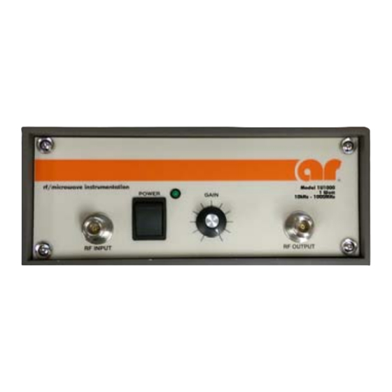
2. OPERATING INSTRUCTIONS GENERAL Operation of the Model 5U1000 broadband amplifier is quite simple. The input signal, whether swept of fixed in frequency, is fed into the jack marked INPUT and the amplifier output signal is taken from the jack labeled OUTPUT. -
Page 22: Power On Sequence
Model 5U1000 POWER ON SEQUENCE Connect input signal to INPUT connector. Connect load to OUTPUT connector. Activate power switch to ON position. A green indicator light will light when power is applied. Rev A... -
Page 23: Theory Of Operation
3. THEORY OF OPERATION INTRODUCTION The Model 5U1000 RF amplifier consists of a single .01-1000 MHz RF amplifier assembly. The power supply section consists of an AC input filter, a circuit breaker, +5V, +15V, and -15V power supplies; a +30V power supply, voltage regulator circuity, an Operate/Control circuit, and an interface board. -
Page 24: Power Supply
Model 5U1000 3.2.1.3 A3 5W Amplifier Assembly (Schematic 10043496) The 5W Amplifier Assembly has two gain stages (U1 and Q1) that have a combined gain of approximately 37 dB. The output RF power is greater than 3.5W at the 1 dB compression point POWER SUPPLY Refer to Schematic Diagram 10044273. -
Page 25: Maintenance
4. MAINTENANCE GENERAL MAINTENANCE INFORMATION The Model 5U1000 should require very little maintenance since it is a relatively simple instrument. It is built with etched circuit wiring and solid state devices which should ensure long, trouble free life. However, should trouble occur special care must be taken in servicing to avoid damage to the devices or the etched circuit board. -
Page 26: Green Power Indicator Led Doesn't Light
Refer to Schematic Number 10044273. 1. Is the cooling fan running? 2. If the fan is not running, check to see that the 5U1000 is plugged into a live outlet. Check the line cord, is the line cord plugged into the 5U1000 completely? 3. -
Page 27: Low Or No Rf Power Output (Rf Test)
The Model 5U1000’s typical gain response at 0 dBm input and -20 dBm input is shown in Figure 4-1 and Figure 4-2. The actual gain may vary considerably from that shown in Figure 4-1 but should be ≥ 37.0 dBm. -
Page 28: Servicing Etched Circuit Boards
Model 5U1000 SERVICING ETCHED CIRCUIT BOARDS When soldering leads, use a hot 40-watt or smaller iron. Apply heat sparingly to the leads, not to the printed wiring on the board. Before installing new parts, clean holes to receive new part without forcing. Have new leads tinned to receive solder quickly with a minimum of heat and without residue. - Page 29 (3) years from date of shipment shown on AR RF/Microwave Instrumentation invoice.
Need help?
Do you have a question about the 5U1000 and is the answer not in the manual?
Questions and answers