Table of Contents
Advertisement
OPERATION and MAINTENANCE
This manual contains important safety information.
Do not destroy this manual.
This manual must be available to the personnel who operate and maintain this compressor.
Doosan Infracore Portable Power
1293 Glenway Drive
Statesville, N.C. 28625
DoosanPortablePower.com
P/N: 46553446 (9-2013) Rev C
MANUAL
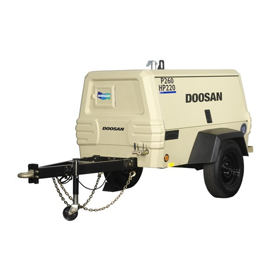
COMPRESSOR MODEL
P260/HP220WYM-T3 (D82)
P260/HP220WYM-FX-T3 (E55)
P260/HP220WYM-EX-T3 (E56)
Advertisement
Table of Contents
Troubleshooting

Related Manuals for Doosan P260/HP220WYM-T3


Summary of Contents for Doosan P260/HP220WYM-T3
- Page 1 P260/HP220WYM-EX-T3 (E56) This manual contains important safety information. Do not destroy this manual. This manual must be available to the personnel who operate and maintain this compressor. Doosan Infracore Portable Power 1293 Glenway Drive Statesville, N.C. 28625 DoosanPortablePower.com P/N: 46553446 (9-2013) Rev C...
-
Page 3: Table Of Contents
TABLE OF CONTENTS TITLE PAGE FOREWORD ............1-3 Information . - Page 4 TABLE OF CONTENTS TITLE PAGE MAINTENANCE ............6-43 Maintenance .
-
Page 5: Foreword
FOREWORD... -
Page 6: Information
Operation & Maintenance Manual FOREWORD Information The contents of this manual are considered to be proprietary and confidential to Doosan Infracore Portable Power (herein referred to as “Portable Power”), and should not be reproduced without the prior written permission of Portable Power. - Page 7 FOREWORD Operation & Maintenance Manual This compressor should not be used: A. For direct or indirect human consumption of the compressed air. B. Outside the ambient temperature range specified in the general data section of this manual. C. When an actual or foreseeable risk of hazardous levels of flammable gases or vapors exists.
- Page 8 Operation & Maintenance Manual FOREWORD...
-
Page 9: Drawbar Notice
DRAWBAR NOTICE... - Page 10 Operating & Maintenance Manual DRAWBAR NOTICE Sketch). DRAWBAR NOTICE (Important) 8. Temporarily support drawbar and move jack from front of compressor to side of This machine may have been shipped from drawbar. the factory with the drawbar positioned upright. To Convert From Shipping Position to Towing Position The following tools are required: Ratchet...
- Page 11 DRAWBAR NOTICE Operating & Maintenance Manual...
- Page 12 Operating & Maintenance Manual DRAWBAR NOTICE...
-
Page 13: Safety
SAFETY... -
Page 14: Safety Precautions
Operating & Maintenance Manual SAFETY Safety Precautions General Ensure that the operator reads and understands the decals and consults the manuals before maintenance or operation. Ensure that the Operation and Maintenance manual, and manual holder if equipped, are not removed permanently from the machine. Ensure that maintenance personnel are adequately trained, competent and have read the manuals. - Page 15 SAFETY Operating & Maintenance Manual Never operate the engine of this machine inside a building without adequate ventilation. Avoid breathing exhaust fumes when working on or near the machine. Do not alter or modify this machine. A battery contains sulfuric acid and can give off gases which are corrosive and potentially explosive.
- Page 16 Operating & Maintenance Manual SAFETY...
- Page 17 SAFETY Operating & Maintenance Manual Steps for determining correct load limit - 1. Locate the statement “The weight of cargo should never exceed xxx kg or xxx lbs” on your vehicle’s placard. 2. This figure equals the available amount of cargo and luggage load capacity. 1.
- Page 18 Operating & Maintenance Manual SAFETY...
- Page 19 SAFETY Operating & Maintenance Manual...
- Page 20 Operating & Maintenance Manual SAFETY Look for these signs on machines shipped to markets in North America, which point out potential hazards to the safety of you and others. Read and understand thoroughly. Heed warnings and follow instructions. If you do not understand, inform your supervisor. DANGER DANGER (Red Background) indicates an imminently hazardous situation which, if not avoided, will result in death or serious injury.
- Page 21 SAFETY Operating & Maintenance Manual...
- Page 22 Operating & Maintenance Manual SAFETY Table 1: FREE SAFETY DECALS Safety Decals are available free of charge. Safety Decals are identified by the decal heading: DANGER, WARNING, or CAUTION. Decal part numbers are on the bottom of each decal and are also listed in the compressor’s parts manual.
-
Page 23: Noise Emission
NOISE EMISSION... -
Page 24: This Section Pertains Only To Machines Distributed Within The United States
Operating & Maintenance Manual NOISE EMISSION Noise Emission This section pertains only to machines distributed within the United States. WARNING Tampering with Noise Control System Prohibited Federal law prohibits the following acts or the causing thereof: 1. The removal or rendering inoperative by any persons, other than for purposes of maintenance, repair, or replacement, of any device or element of design incorporated into any new compressor for the purpose of noise control prior to its sale or delivery to the ultimate purchaser or while it is in use;... -
Page 25: Noise Emission Warranty
NOISE EMISSION Operating & Maintenance Manual Noise Emission Control Maintenance Log COMPRESSOR MODEL __________________________ SERIAL NO. ___________________________________ USER UNIT NO. ________________________________ UNIT IDENTIFICATION DEALER OR DISTRIBUTOR FROM WHOM PURCHASED: Engine Make & Model: ________________ __________________________________ Serial No.: _________________________ __________________________________ Purchaser or Owner: _________________ __________________________________ Address: __________________________ Date Purchased: ____________________... - Page 26 Operating & Maintenance Manual NOISE EMISSION Maintenance Schedule Item Area Period Compressed Air Leaks As Detected Safety and Control Systems As Detected Acoustic Materials Daily Fasteners 100 hours Enclosure Panels 100 hours Air Intake & Engine Exhaust 100 hours Cooling Systems 250 hours Isolation Mounts 250 hours...
- Page 27 NOISE EMISSION Operating & Maintenance Manual every 250 hours of use. Any discrepancies found should be corrected before placing the unit back in operation. Unrestricted airflow over the radiator and oil cooler must be maintained at all times during operation. H.
- Page 28 Operating & Maintenance Manual NOISE EMISSION Maintenance Record For Noise Emission Control And Extended Warranty Item Hourmeter Maint/inspect Location Work Done Description Of Work Reading Date City/state By (Name)
-
Page 29: General Data
GENERAL DATA... -
Page 30: Unit Model
Operating & Maintenance Manual GENERAL DATA General Data Unit Model: UNIT MODEL P260/HP220WYM CFM (litres/sec) 260 (123) / 220 (104) Engine Speed - RPM (Full Load) 2500/2150 Engine Speed - RPM (No Load) 1600 COMPRESSOR Rated Operating Pressure - psi (kPa) 100 (689) / 150 (1034) Safety Valve Setting - psi (kPa) 200 (1380) -
Page 31: Expendable Service Parts
22226351 Engine Fuel Filter Element 16539462 Fuel Water Separator Element 22926737 WARNING Modification or alteration of this machine. Can result in severe injury or death. Do not modify or alter without the express written consent of Doosan Infracore Portable Power. - Page 32 Operating & Maintenance Manual GENERAL DATA...
-
Page 33: Operation
OPERATION... -
Page 34: Before Towing
Operating & Maintenance Manual OPERATION Before Towing WARNING Failure to follow these instructions CAN cause severe injury or death. • Ensure tow vehicle has towing capacity for weight of this unit as stated on general data decal. • Position the tow vehicle to align its hitch with the pintle eye or coupler of the compressor. -
Page 35: Towing
OPERATION Operating & Maintenance Manual Towing DISCONNECT • Engage tow vehicle parking brake. • Chock tires of compressor. • Set the vehicle parking brake. Chock wheels of unit. • Standing to the side, remove pin from tube of jack. • Disconnect safety chains. Crank jack to raise eye or coupler from hitch. Tow vehicle can be moved. - Page 36 Operating & Maintenance Manual OPERATION 8. Engine Tachometer - Indicates engine speed in RPM from 0 when stopped to full speed. (Optional) 9. Service Air Button - Push to engage. Allows user to load compressor after engine warm-up. 10. Fuel Level Gauge - Optional 11.
- Page 37 OPERATION Operating & Maintenance Manual WARNING Unrestricted air flow from a hose will result in a whipping motion of the hose which can cause severe injury or death. A safety device must be attached to the hose at the source of supply to reduce pressure in case of hose failure or other sudden pressure release.
- Page 38 Operating & Maintenance Manual OPERATION Starting • Turn the POWER switch to “ON”. • Turn Power switch to “START” position to crank engine. Hold switch in “START” position for approximately 5 seconds after engine starts. NOTICE Do not operate the starter motor for more than 30 seconds without allowing at least 30 seconds cooling time between start attempts.
- Page 39 OPERATION Operating & Maintenance Manual Two Pressure Mode Operation The P260/HP220WYM compressor is capable of operating at two different modes: 1. The low pressure mode is activated by pressing the LO-HI pressure switch to the LO position. In this mode, the compressor will regulate according to air demand, between 0 and 260 cfm at 100 psi regulated set pressure.
- Page 40 Operating & Maintenance Manual OPERATION • WARNING Since the service valve is closed, air downstream of the valve may be trapped. A vent hole in the service valve will slowly bleed air from the hose. Do not disconnect hoses until all pressure has been vented. NOTICE Do not wire around or bypass a shutdown sensor or switch.
- Page 41 OPERATION Operating & Maintenance Manual • P260/HP220WYM Pressure Regulator Adjusting Instructions High Pressure Regulator Low Pressure Regulator Before Starting 1. Put HI/LO pressure switch in LO position. 2. At the low pressure regulator, loosen the jam nut and turn screw counterclockwise until tension is no longer felt at the screw.
- Page 42 Operating & Maintenance Manual OPERATION Center Bar Blinking Compressor is ready to start (no faults) Engine Model Not Compressor will start and operate with a 1700-2300 rpm range. Recognized Engine ECM SECU cannot communicate with engine ECM over J1939 CAN BUS. Communication Failure Pre-Heat Signal or Start Displayed while ignition switch is in the pre-heat or start position.
-
Page 43: Lubrication
LUBRICATION... -
Page 44: Portable Compressor Fluid Chart
C to 52 Alternate: ISO Viscosity Grade 46 with rust Preferred Fluids - Use of these fluids with and oxidation inhibitors, designed original Doosan branded filters can extend for air compressor service. airend warranty. Refer to operator’s manual 350 psi Preferred:... -
Page 45: Maintenance
MAINTENANCE... -
Page 46: General
Operating & Maintenance Manual MAINTENANCE Maintenance CAUTION Any unauthorized modification or failure to maintain this equipment may make it unsafe and out of factory warranty. If performing more than visual inspections, disconnect battery cables and open manual blowdown valve. Use extreme care to avoid contacting hot surfaces (engine exhaust manifold and piping, air receiver and air discharge piping, etc.). -
Page 47: Air Cleaner
MAINTENANCE Operating & Maintenance Manual Air Cleaner If this unit is equipped with the Optional Full Instrumentation, the SECU Module, located inside front panel near instrument panel, will Display #9 when either engine or compressor air filter is restricted. Weekly squeeze the rubber valve (precleaner dirt dump) on each air cleaner housing to ensure that they are not clogged. -
Page 48: Fasteners
Operating & Maintenance Manual MAINTENANCE Tires A weekly inspection is recommended. Tires that have cuts or cracks or little tread should be repaired or replaced. Monthly check the wheel lug nuts for tightness. Fasteners Visually check entire unit in regard to bolts, nuts and screws being properly secured. Spot check several capscrews and nuts for proper torque. - Page 49 MAINTENANCE Operating & Maintenance Manual Premature wear of both the engine and compressor is ASSURED whenever dust-laden air is permitted to enter the engine’s combustion chamber or compressor intake. The flexible hoses used in the fuel, oil and air lines on these units are primarily used for their ability to accommodate relative movement between components.
-
Page 50: Compressor Oil Cooler
Operating & Maintenance Manual MAINTENANCE NOTICE Installing a new oil filter element when the old gasket remains on the filter head, will cause an oil leak and can cause property damage. 4. Lubricate the new filter gasket with the same oil being used in the machine. 5. -
Page 51: Receiver-Separator Systems
MAINTENANCE Operating & Maintenance Manual Receiver-Separator Systems WARNING High pressure air can cause severe injury or death from hot oil and flying parts. Always relieve pressure before removing caps, plugs, covers or other parts from pressurized air system. • Open service valve at end of machine. •... -
Page 52: Scavenge Line
Operating & Maintenance Manual MAINTENANCE Scavenge Line WARNING High pressure air can cause severe injury or death from hot oil and flying parts. Always relieve pressure before removing caps, plugs, covers or other parts from pressurized air system. The scavenge line originates at the manifold and terminates at the compressor airend near the oil filter element. - Page 53 MAINTENANCE Operating & Maintenance Manual Field Repair of Texture Paint 1. The sheet metal should be washed and clean of foreign material and then thoroughly dried. 2. Clean and remove all grease and wax from the area to be painted using Duponts 3900S Cleaner prior to sanding.
-
Page 54: Maintenance Schedule
Operating & Maintenance Manual MAINTENANCE MAINTENANCE SCHEDULE Daily Weekly Monthly 3 MOS. 6 MOS. 12 MOS. 250 hours 500 hours 1000 hours Compressor Oil Level Engine Oil Level Radiator Coolant Level Gauges/Lamps Air Cleaner Service Indicators Fuel Tank (fill at end of day) DRAIN Fuel Water Separator (Drain) Oil Leaks... -
Page 55: Troubleshooting
TROUBLESHOOTING... -
Page 56: Introduction
Operation & Maintenance Manual TROUBLESHOOTING Troubleshooting B. Do The Simplest Things First Most troubles are simple and easily corrected. For example, most complaints are Introduction “low capacity” which may be caused by too low an engine speed or “compressor over- Troubleshooting for a portable air heats”... -
Page 57: Trouble Shooting Chart
TROUBLESHOOTING Operating & Maintenance Manual Trouble Shooting Chart Bold Headings depict the COMPLAINT - Subheadings indicate CAUSES NOTE: Subheadings suggest sequence to follow troubleshooting. Table 1: Machine Shutdown Cause Corrective Action Out of fuel Add CLEAN diesel fuel. Low fuel shutdown (option) Add CLEAN diesel fuel. - Page 58 Operating & Maintenance Manual TROUBLESHOOTING Table 3: Machine Will Not Run Cause Corrective Action Out of fuel Add clean diesel fuel. Low fuel shutdown (option) Add clean diesel fuel. See table 11. Airend discharge temperature too high See table 4. Separator temperature to high See table 5.
- Page 59 TROUBLESHOOTING Operating & Maintenance Manual Table 5: High Separator Temperature Shutdown SECU CODE 2 Cause Corrective Action Dirty cooler Clean cooler. Low compressor oil level Add oil. Check for leaks. Clogged compressor oil filter elements Replace elements. Change oil. Operating pressure too high Reduce pressure setting to within spec.
- Page 60 Operating & Maintenance Manual TROUBLESHOOTING Table 7: High Engine Coolant Temperature Shutdown SECU CODE 4 Cause Corrective Action Dirty cooler Clean cooler. Dirty operating conditions Relocate machine to cleaner environment. Machine out of level>15 degrees Relocate or level machine. Ambient temperature>120°F (49°C) Above spec.
- Page 61 TROUBLESHOOTING Operating & Maintenance Manual Table 11: Low Fuel Shutdown (Option) SECU CODE 8 Cause Corrective Action Out of fuel Add clean diesel fuel. Jumper disconnected (standard Reinstall jumper. Refer to wiring decal. machine) Low fuel shutdown/gauge sensor Check harness connections. Replace sensor. malfunction SECU controller malfunction Check harness connections.
- Page 62 Operating & Maintenance Manual TROUBLESHOOTING Table 16: Generator Switch on SECU CODE H (Electronic Engine Models Only) Cause Corrective Action Machine will not start Switch generator to the air only position. Generator switch malfunction Check harness connections. Replace switch. SECU controller malfunction Check harness connections.
- Page 63 TROUBLESHOOTING Operating & Maintenance Manual Table 21: Oil Seal Leak Cause Corrective Action Contaminated Lube Oil Drain and flush system. Add new CLEAN oil. Replace seal. Malfunctioning Seal Consult dealer. Replace seal. Scored Shaft See instructions in new seal kit. Table 22: Will Not Unload Cause Corrective Action...
-
Page 64: Engine Diagnostic Codes
Operating & Maintenance Manual TROUBLESHOOTING Engine Diagnostic Codes • Failure flashes can be read on the Engine Failure Lamp when the ON/OFF ignition switch is “ON” or when the unit is running. • The Engine Failure Lamp is located behind the front end panel. •... - Page 65 Revision History Rev Level EC Number Comments SVC xxxxx Original Release CN026142 Doosan Updates CN034824 Added Flex Models to Front Cover...
- Page 66 Doosan Infracore Portable Power 1293 Glenway Drive Statesville, N.C. 28625 www.doosanportablepower.com ©2012 Doosan Infracore Portable Power Printed in the U.S.A.
Need help?
Do you have a question about the P260/HP220WYM-T3 and is the answer not in the manual?
Questions and answers