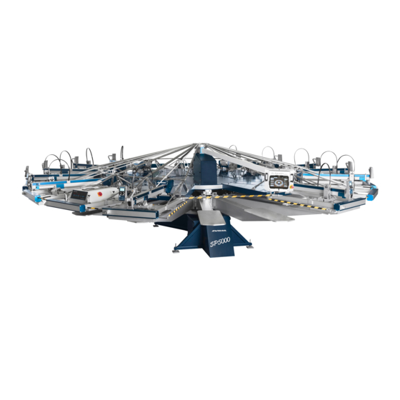
MHM SYNCHROPRINT 5000 Wiring Diagram
Hide thumbs
Also See for SYNCHROPRINT 5000:
- Wiring diagram (16 pages) ,
- Operating instructions manual (52 pages)
Table of Contents
Advertisement
Available languages
Available languages
Quick Links
Verdrahtungsplan
wiring diagram
SYNCHROPRINT 5000
STEP Platine
Servo Platinen
Master Einheit
Not-Halt Relais
Terminal Einheit
M-Touch Pro
Servoverstärker
Wechselstromverteiler 400V
Wechselstromverteiler 210V
AC Verteilerplatine
24V Netzteil
Inhalt:
Seite / page
Deckblatt
..........
..........
..........
..........
..........
..........
..........
..........
..........
..........
..........
..........
..........
..........
..........
Contents:
..........
1
cover sheet
..........
2
block diagram
..........
3
squeegee arm part 1
..........
4
..........
5
..........
6
..........
7
..........
8
..........
9
..........
10
..........
11
..........
12
..........
AC- rack 210V
13
..........
14
..........
15
Wiring diagram
SP5000
Deckblatt/
cover sheet
REV 1.3
Seite/page 1
Advertisement
Table of Contents

Summary of Contents for MHM SYNCHROPRINT 5000
-
Page 1: Table Of Contents
Verdrahtungsplan wiring diagram SYNCHROPRINT 5000 Inhalt: Seite / page Contents: Deckblatt ....cover sheet ....Blockschaltbild block diagram Rakelarm Teil 1 ....squeegee arm part 1 Rakelarm Teil 2 ....squeegee arm part 2 STEP Platine .. -
Page 2: Blockschaltbild
Wiring diagram SP5000 Blockschaltbild/ block diagram REV1.3 Seite/page 2... -
Page 3: Rakelarm Teil 1
07-0-0-10002-0 CLEAN Station unit manual 20-0-0-0439-0 A1 & A2 Station unit automatic 20-0-0-0962-0 Magnetventil Rakel/ electromagnetic valve squeegee MHM-Automatic-Module-Rev2 20-0-0-0555-3 05-3-3-0038-0 A2J1 all station switch off X2-A4X7 on the first station switch on weiss/white Step Platine/ gelb/yellow Step PCB grün/green... -
Page 4: Rakelarm Teil 2
Frequenzumrichter 200V frequency converter 1Phase 07-0-0- 0133 HITACHI RUN PWR Wj200 INVERTER 8.8.8.8. STOP RESET A14J2 V3000 SN 7 L PLC P24 Seite/ page 14 SP E0 EA H O OI L AM Cm2 12 11 L1 PE N Trocknerbuchse/ drier socket 07-0-0-0135-0 color FU... -
Page 5: Step Pcb
X4 klemmblock oben/ Step Platine/ upper DC block step PCB Seite/page 15 05-3-3-0037-0 xgnd MHM-3SMK24V-1A_Rev2 Schrittmotor / stepping motor B1 ... rosa/pink braun/brown B2 ... gelb/yellow schwarz/black Y-Achse hinten / rear Y-axis orange/orange A2 ... weiß/white A1 ... grün/green... - Page 6 Hubventil/ lift valve Palettenentriegelungsventil/ Adjust Hubventil/ change pallet sensor change pallet valve adjust lift valve schwarz/black #2...S 07-0-0-0020-0 schwarz/black #1...+ blau/blue schwarz/black braun/brown weiss/white grau/grey blau/blue grün/green schwarz/black braun/brown gelb/yellow braun/brown blau/blue schwarz/black braun/brown Off Kontakt Motor/ off contact motor 07-0-0- 0544 Servo Platine/...
-
Page 7: Servo Pcb
Folientastatur Station/ keypad station 07-0-0-10002-0 CLEAN Master Einheit/ master unit 20-0-0-0438-0 05-3-3-10103-0 Switch S1 to off UNIT CONTROL Rev2 05-3-3-10101-0 A6J1 A5J1 Servo Platine servo PCB Seite/page 6 Wiring diagram P 000 Master Einheit/ master unit REV 1.3 Seite/page 7... -
Page 8: Safety Device
brown Safety white yellow station green Not-Aus-Kreis 2.0 Sicherheitskreisplatine/ STATION 11 SPARE 5 A7J3 safetyline PCB 05-3-3-3011-1 STATION 9 SPARE 4 STATION 7 SPARE 3 SPARE 2 STATION 5 STATION 3 SPARE 1 STATION 1 STATION 12 SIGNALS A J2 A J1 24V DC SAFETYLINE PCB 2.0... - Page 9 Folientastatur Terminal Front/ keypad terminal front 07-0-0-10003-0 SELECT SAMPLE START CLEAN Terminal Control 05-3-3-10102-0 A9J2 Terminal Modul Seite/page 10 UNIT CONTROL Rev2 Switch S1 to ON 05-3-3-10101-0 A9J1 A5J4 Servo Platine/ Not Halt Taster/ PCB servo Emergency Seite/page 6 stop button 20-0-0-0490-0 Verteilerplatine/ braun/brown ...
-
Page 10: Terminal Unit
Samsung Galaxy View 07-0-0-0546-0 Terminal Modul PCB 05-3-3-10104-0 A9J2 Terminal Einheit terminal unit MHM-TERMINAL-MODUL_REV2 Seite/page 9 weiss/white schwarz/black Funk Antenne/ radio antenna Off ... 5VDC On ... 19VDC Wiring diagram SP5000 M-Touch Pro/ m-touch pro REV 1.3 Seite/page 10... -
Page 11: Servo Drive
Servoverstärker/ servo drive 0 -0-0- 00 -0 A13.1 CAN Operator/ KEB F5V2 operator CAN 90-0-0-3002-1 START ENTER FUNC SPEED STOP A11X6B +24V schwarz #1/black #1 Klemmblock unten lower DC bloc schwarz #2/black #2 Seite/ page 15 Servo_STO braun/brown ... Q1 Sicherheitsschaltgerät/ Servo_Quickstop safety device... -
Page 12: Ac- Rack 400V
Hauptschalter/ mains switch 07-0-0-0008-1 Brücke/ commoning link 07-0-0-0094-0 N L1 L2 L3 PE PKZM0-6,3 PKZM0-10 6,3A protective breaker protective breaker 07-0-0-0093-0 07-0-0-0092-0 Setting: 6,3A Setting: 4A A1231 AC Verteilerplatine/ Servoverstärker/ AC distribution PCB servo drive Seite/page 14 Seite/page 11 Wiring diagram SP5000 Wechselstromverteiler 400V/ AC- rack 400V... - Page 13 Hauptschalter/ mains switch 07-0-0-0008-0 Transformator 210/400V transformer 210/400V L1 L2 L3 PE PKZM0-6,3 6,3A PKZM0-10 protective breaker protective breaker 07-0-0-0092-0 07-0-0-0093-0 Setting: 10A Setting: 4A A13J1 AC Verteilerplatine/ Servoverstärker/ AC distribution PCB servo drive Seite/page 14 Seite/page 11 Wiring diagram SP5000 Wechselstromverteiler 210V/ AC- rack 210V...
-
Page 14: 24V Power Supply
Y-Schaltung/ Y- onnection (3x400V) -Schaltung/ -connection (3x210V) X3Q1 Motorschutzschalter/ protective breaker Seite/page 12-13 A14 V3000 -0-0-0371- 14 1 Sicherung Sicherung Sicherung Fuse Fuse Fuse N/L3 N/L2 N/L1 X Rakelarm 1 X Rakelarm 13 X Rakelarm 2 X Rakelarm 14 X Rakelarm 3 X Rakelarm 15 X Rakelarm 4 X Rakelarm 16... - Page 15 capacitor C-TEC 24 20 8 - UPS Kondensator C-TEC 24 20 8 - USV 07-0-0-0540-0 Netzteil 20A/ Klemmblock oben/ supply power 20A upper DC block C-TEC 07-0-00166-1 rot/red schwarz/black IO-1 Shutdown Netz +V +V -V -V Mains Vcap. Fehler Fault MEAN WELL NDR-480-24 Betrieb / Operation...


Need help?
Do you have a question about the SYNCHROPRINT 5000 and is the answer not in the manual?
Questions and answers