Table of Contents
Advertisement
Owner's Manual
Model
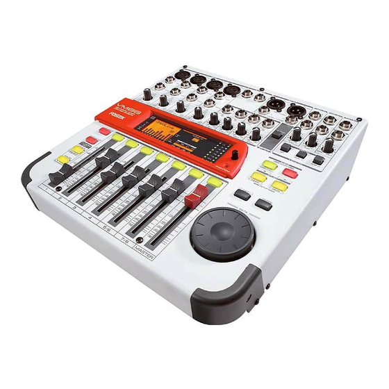
Eight Channel Digital Mixer with DSP Effects
Introduction
Thank you very much for purchasing the Fostex VM88.
Please read the following to get the most satisfaction from your purchase, and to
learn important information about safety precautions when using Fostex prod-
ucts.
The VM88 digital mixer does all internal signal processing digitally.
The input features 8 analog channels, of which 4 channels (XLR or PHONE) are for
microphones; digital inputs (S/P DIF or ADAT) via optical connection are provided.
For outputs, an optical digital output (S/P DIF or ADAT) in addition to stereo out
(balanced/unbalanced), headphone out, AUX send/out and monitor outs in analog
are also provided. An insert function is featured in channels 1 - 4 for more
flexibility during mixing.
In addition to each input channel, an three band EQ is also provided for the
master output. The VM88 also incorporates high performance DSP multi-effects
on two channels that operate by A.S.P. (Fostex Advanced Signal Processing Tech-
nology*) exclusively developed by Fostex. This allows a wide range of equalizing
and effects processing. All settings, including mix and effects settings, are stored
in scene memory, and a desired scene memory can be recalled instantaneously.
Although small and lightweight, the VM88 is a high performance unit. Please
read this manual carefully before operation to understand all functions of the
VM88.
* See page 24 for more details on the A.S.P. (Fostex Advanced Signal Processing Technology).
Advertisement
Table of Contents

Related Manuals for Fostex VM88


Summary of Contents for Fostex VM88
- Page 1 Although small and lightweight, the VM88 is a high performance unit. Please read this manual carefully before operation to understand all functions of the VM88. * See page 24 for more details on the A.S.P. (Fostex Advanced Signal Processing Technology).
- Page 2 Servicing - The user should not attempt to service the appliance beyond that described in the operating instructions. All other servicing should be referred to qualified service personnel. < IMPORTANT! > Equipment name, electrical ratings, serial number and other infor- mation for the VM88, are written on bottom side.
-
Page 3: Table Of Contents
These things may cause electric shock or short circuit the VM88, and damage it. If the VM88 should become wet, unplug the power cable from the AC outlet, and contact your authorized service station. -
Page 4: Names And Functions
Model VM88 Owner’s Manual Names and Functions Top panel section 1. Input connector External sound sources are input here. MIC 1 - 4 are for Canon connectors (XLR-3-31; pin 2=hot), which comply to mic/line signals. The input gain can be trimmed within a range of -50dBu ~ - 10dBu. - Page 5 For details, please refer to “Connecting peripheral equipment” on page 9. 7. Foot switch connecting jack A foot switch (Fostex Model 8051) is plugged in here. The foot switch function can be changed by the [SETUP mode] explained later. The initial setting recalls the scene memory.
- Page 6 Model VM88 Owner’s Manual can be setup. Refer to [Channel parameter edit mode] on page 20 for details. 25. Fader adjust key This key warns by blinking if a fader position drifts or sound volume is accidentally changed at switch ON of power or at recall of the scene memory.
-
Page 7: Rear Panel Section
4. AC IN connector [AC IN] Plug-in the power cable included with the VM88 here. < NOTE > If the VM88 is not to be used for long periods (more than one month) be sure to remove the power cable plug from the wall outlet. -
Page 8: Before Operation
If reset is executed with the INPUT and MASTER raised simultaneous with start up of this unit, the LEVEL ADJUST key/FADER ADJUST key will blink. This indicates that the VM88 has entered the Level Adjust Mode/Fader Adjust Mode because of the difference between present fader position and the fader position at start up following reset. -
Page 9: Peripheral Equipment Connection
Peripheral Equipment Connection Sound sources and external equipment shown in the examples below can be connected to the VM88’s input and output connectors. When connecting external equipment to the in/out connectors, be sure to switch off power to the VM88. - Page 10 * The Canon connector and TRS phone jack of each channel cannot be used in parallel. Use either input only. A malfunction could occur if both are used at the same time. * Be sure to switch off the power to the VM88 or switch off the phantom power when plugging or unplugging microphone cables.
- Page 11 < Please remember! > If a digital signal (S/P DIF or ADAT) is to be input to VM88 or a digital signal (S/P DIF or ADAT) is to be output from the VM88, it will be necessary to setup the system clock and DIGITAL IN or DIGITAL OUT modes.
-
Page 12: Application Examples
Model VM88 Owner’s Manual The following are actual examples in application of VM88 and could be helpful in your application. < Example 1 > : As a live performance keyboard mixer The VM88 can be used as a submixer for keyboards and sound source modules. - Page 13 To use as a MONO IN/STEREO OUT effects The VM88 internal DSP multi-effects can be utilized for high quality external processing by connecting the VM88 ST OUT L, R to the FD-8 AUX RTN L, R jack. If the input channel fader is set “0” and the EFF BUSS is sent via the pre-fader, the effects sound only can be output from ST OUT.
- Page 14 [20] but the preset scene [00] cannot be changed. Refer to page 30 for details on the scene memory. * If, for some reason, you would like to return the VM88 setting to the factory default figure, refer to [Reset of VM88] on page 8.
-
Page 15: Normal Mix Mode
When the VM88 is in [Initial state of VM88], as explained in the previous section, if the INPUT fader of the channel to which a signal is being input (Example: The channel 1 INPUT fader if a sound source is connected to INPUT 1.) and the MASTER fader is raised, signals will be output from the STEREO OUT L, R jacks... - Page 16 On/off of the stereo out L, R signals The stereo L, R output signals from ST OUT L, R connectors (balanced/unbalanced) can be set to on or off by the VM88 top panel ST OUT ON/OFF switch. This is ON ( Outputs from ST OUT L, R connectors (balanced/unbalanced) can be switched ON or OFF.
- Page 17 [Fader adjust mode] explanation. * To set to the present fader position: Press the flashing LEVEL ADJUST key and the VM88 will enter the level adjust mode. Then setup by following [Level adjust mode] on page 31.
- Page 18 < NOTES > * If the VM88 is used as a slave with the system clock set to [INT], noise will occur. Therefore, if the system clock must be set to [INT], the VM88 must be used as the master machine.
- Page 19 * [DIGITAL] will blink and [44.1kHz] will be lit when the setup mode DIGITAL IN setting is in other than OFF and DIGITAL IN is incorrectly locked. In other words, this indicates that the VM88 is operating switched to the internal clock (44.1kHz).
-
Page 20: Channel Parameter Edit Mode
Twelve items, as shown in list below, can be set by the channel parameter edit mode. Regard- less of the VM88’s current mode, their respective edit modes can be entered by executing the key operations listed below. To exit from the channel parameter edit mode, press the EXIT key. -
Page 21: Setup Method Of The Effect Send Level
The VM88 is set to POST (post fader) in the initial state. <Useful information!> * The EFFECT SEND signal adjusted in channels 1 ~ 4, 5/6 and 7/8 is sent to the VM88 internal DSP multi-effects (EFF1 or EFF 2). The operating explanation used here is based on the effects type ([Norm. -
Page 22: Setup Method Of The Aux Send Level
AUX SEND jack. The same as with the EFFECT SEND signal, either POST or PRE can be selected for the AUX SEND signal. The VM88 is set to POST in the initial state. To change the setting, please see below [Setup of PRE/POST]. -
Page 23: Pre/Post Setup Method
Blinking 2. Press the desired CH ON/CH SEL key and select the channel you wish to adjust. Model VM88 Owner’s Manual 3. Adjust the number with the DATA encoder. [Pre] or [Post] can be selected. The graphic display will also change at the same time. -
Page 24: Effect Edit Mode
Model VM88 Owner’s Manual The VM88 offers high quality ambient effects by employing the A. S. P. (Fostex Advanced Signal Processing Technology), which is exclusively developed by Fostex. With the A. S. P., you can obtain an incomparably clean and high density Hall Reverb, overwhelmingly clear Room Re- verb and wonderfully hi-fidelity Plate Reverb. -
Page 25: About The Effect Types
About the effect types The VM88 contains two independent DSP multi-effect units; EFF 1 and EFF 2. A variety of effect types are preset for each effect unit. By selecting a suitable effect type, you can process the sound as you wish. You can also edit the parameters of the selected effect type to create your own effect sounds. -
Page 26: Selecting The Effect Type
Model VM88 Owner’s Manual Effect types preset for EFF 2 Name Parameter type 1~28 are the same effect types as the EFF 1 presets listed on the preceding page. (For details refer to the preceding page.) MonoDELAY DELAY PanDELAY DELAY... -
Page 27: Effect Parameter Settings
The foot switch can be used to switch muting on/off for effect 1 or effect 2, or can simultaneously mute both effect 1 and effect 2. For details refer to page 33 “Setup mode.” Model VM88 Owner’s Manual Details on the parameters are given in the following section, "Parameter settings."... -
Page 28: Effect Parameter Details
Model VM88 Owner’s Manual Effect parameter details The parameters that can be adjusted will depend on the parameter type. Reverb effect parameters (parameter type: REVERB) For effect types 1--24 of the preceding "Effect type" table, the following four parameters can be ad- justed. - Page 29 2) * The ENTER key / foot switch can be used for tap input (refer to page 27). 4. FEEDBACK Adjust the number of delay repeats. Range: 0--99 (100 steps in increments of 1) Model VM88 Owner’s Manual...
-
Page 30: Scene Memory Mode
Model VM88 Owner’s Manual The VM88 provides 21 scene memories (scene numbers 00--20). Of these, scene number [00] is a preset scene named "Initial Mix," and cannot be modified by the user. Your own settings can be stored in scene numbers [01]--[20]. Each scene stores the contents of Normal Mix mode, Channel Parameter Edit mode, and Effect Edit mode as a set. -
Page 31: Level Adjust
FADER ADJUST key/LEVEL ADJUST key will blink to indicate that the fader locations before the VM88's power is turned off are different than the fader locations when the power was turned on. 1. Press the FADER ADJUST key. -
Page 32: Directly Recalling A Scene Memory
Model VM88 Owner’s Manual Directly recalling a scene memory In addition to the method described earlier in "Scene recall," a scene memory can also be recalled directly using the following method of stepping consecutively through the stored scenes. < NOTE >... -
Page 33: Setup Mode
Using the DIGI IN setup menu, two items - DIGI IN format and input channel - can be set. When the ENTER key is pressed (Step-3) after selecting the DIGI IN setup menu, the VM88 will change to the display to select the DIGI IN format. Then, when the ENTER key <Step-5> is pressed, simultaneous with setup of format, the display will change to the next layer input channel select. - Page 34 <Display> < NOTE > If the system clock is set to [INT], noise will be generated unless the VM88 is used as the master machine. < Please remember! > If there is no external digital signal or DIGITAL IN lock is disengaged, the VM88 will operate by [INT] (Internal clock).
- Page 35 <Please remember the following points when using the phantom power supply!> Do the following before using the phantom power: * When connecting a condenser microphone to MIC INPUT 1-4 (XLR-3-31 type) of the VM88, be sure this microphone requires phantom power (+48V).
- Page 36 Model VM88 Owner’s Manual * Setup menu for peak hold time The LED bar graph meter (excluding the LCD display meter) peak hold time can be set. The setup content will be held even if the main power is switched off.
- Page 37 < Please remember! > When set to [Scene U/D], the VM88 enters the scene direct recall mode when the foot switch is stepped on once, then with each press of the foot switch, the scene number changes in the forward direction.
-
Page 38: The Options
To install the clamper, use the four screws provided on the bottom of the VM88, as indicated by arrows in schematic below. <NOTE!> Do not use the screws included with the clamper as the screw pitch is different. -
Page 39: Specifications
: 10k or more <MON OUT L, R> Connector : ø6mm phone jack/Unbalanced Output level : -10dBV Load impedance : 10k or more Model VM88 Owner’s Manual Specifications <PHONES OUT> Connector Load impedance Output level <Foot Switch> Connector <Others> Equalizer... - Page 40 Model VM88 Owner’s Manual This equipment is compatible with the EMC Directive (89/336/EEC) - Directive on approximation of member nation's ordinance concerning the electromagnetic compatibility and with the Low Voltage Directive (73/23/EEC) - Directive on approximation of member nation's ordinance concerning elec- tric equipment designed to be used within the specified voltage range.
Need help?
Do you have a question about the VM88 and is the answer not in the manual?
Questions and answers