Table of Contents
Advertisement
Quick Links
Thank you very much for purchasing the Fostex FM-3 portable mixer.
To ensure the best performance, read this manual thoroughly before using the unit. Keep this manual handy for
future reference.
Safety Instructions ..................................................................2
Precautions ...............................................................................4
Precautions before using ..........................................................4
Precautions on installation ........................................................4
Main features ............................................................................5
Basic operations .....................................................................6
Preparation of power supply ....................................................6
Prepararion of input channels ..................................................7
Preparation of output channels ...............................................7
Preparation of metering ............................................................7
Preparation of monitoring .........................................................8
Master fader reference setting .................................................8
Input setting ..................................................................................8
Block diagram ..........................................................................9
Names and functions ..........................................................10
Front panel ................................................................................10
Left side panel ...........................................................................12
Right side panel ........................................................................13
Owner's Manual
Portable Mixer
FM-3
Model
Table of contents
Display .......................................................................................14
Adjusting the display brightness ............................................14
Selecting the meter mode ......................................................15
Selecting the status display ....................................................15
Input status display ...................................................................16
T12 power supply mode setting ...................................16
Output status display ...............................................................17
Limiter parameter setting ...............................................18
Meter status display .................................................................19
Parameter setting procedure ........................................19
Parameter details ............................................................19
Peak meter on/off ....................................................19
VU meter reference level ......................................19
Lighting level of peak over indicator .....................20
Internal battery selection ........................................20
System status display ..............................................................20
Initializing the flash memory ...........................................20
Main specifications ..............................................................21
External dimensions ...........................................................23
Advertisement
Table of Contents

Related Manuals for Fostex FM-3


Summary of Contents for Fostex FM-3
-
Page 1: Table Of Contents
Thank you very much for purchasing the Fostex FM-3 portable mixer. To ensure the best performance, read this manual thoroughly before using the unit. Keep this manual handy for future reference. Safety Instructions ...2 Precautions ...4 Precautions before using ...4 Precautions on installation ...4... -
Page 2: Safety Instructions
CAUTION RISK OF ELECTRIC SHOCK DO NOT OPEN CAUTION: TO REDUCE THE RISK OF ELECTRIC SHOCK, DO NOT REMOVE COVER (OR BACK). NO USER - SERVICEABLE PARTS INSIDE. REFER SERVICING TO QUALIFIED SERVICE PERSONNEL. "WARNING" "TO REDUCE THE RISK OF FIRE OR ELECTRIC SHOCK, DO NOT EXPOSE THIS APPLIANCE TO RAIN OR MOISTURE."... -
Page 3: Important Safety Instructions
Important Safety Instructions Read these instructions. Keep these instructions. Heed all warnings. Follow all instructions. Do not use this apparatus near water. Clean only with dry cloth. Do not block any ventilation openings. Install in accordance with the manufacturer's instructions. Do not install near any heat sources such as radiators, heat registers, stoves, or other apparatus (including amplifiers) that produce... -
Page 4: Precautions
<Important!> Equipment name, electrical ratings, serial number and other information for the FM-3, are written on bottom side. Precautions Precautions on installation Do not install the unit in the following conditions. -
Page 5: Main Features
You can monitor signals from the AUX IN input, as well as you can mix them with the main input signals. By connecting the AUX OUT output to the AUX IN input of another FM-3, you can cascade two FM-3 mixers. •... -
Page 6: Basic Operations
Preparation of power supply To operate the unit on internal battery power, set AA alka- line or nickel hydride batteries to the supplied battery box and fit the box to the battery compartment on the right side panel. Make sure to set alkaline or nickel hydride batteries to the battery box in correct direction as marked on the box. Set four batteries on each side of the battery box. -
Page 7: Prepararion Of Input Channels
You can turn on the unit by setting the [POWER] switch on the front panel to “INT” (upper position) or “EXT” (lower position). When you operate the unit on internal battery power, set the switch to “INT”. When you operate the unit on external power, set it to “EXT”. When you turn on the unit for the first time, the display shows the stereo VU meters as shown below. -
Page 8: Preparation Of Monitoring
Preparation of monitoring Connect headphones to the 1/4-inch [PHONES] jack on the front panel or the mini-phone [PHONES] jack on the right side panel. You can use both the 1/4-inch and mini-phone jacks simultaneously. Set the monitor select switch to “ST” and adjust the monitor level using the [PHONE] control. -
Page 9: Block Diagram
Block diagram... -
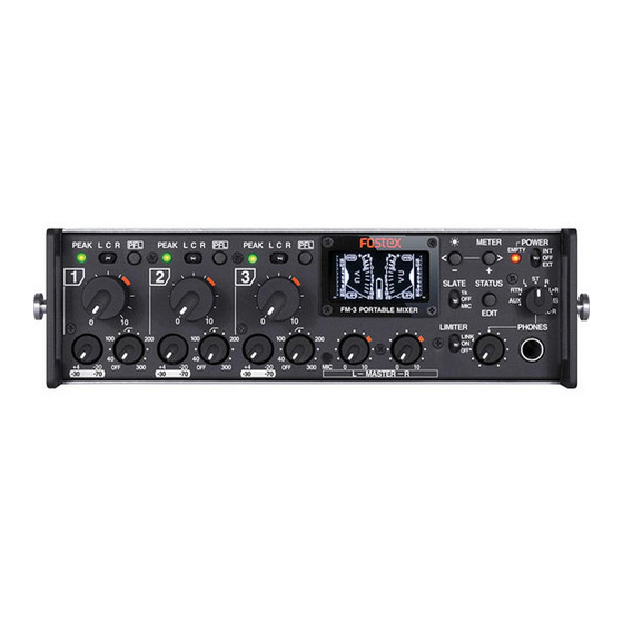
Page 10: Names And Functions
Front panel section PEAK indicators (1 through 3) Each indicator lights according to the signal level of the corresponding input channel as follows. Lighting level Color (compared with the reference level) Approximately -12dB below Green +8dB the internal maximum level Approximately -3dB below +17dB the internal maximum level... - Page 11 Monitor select switch This switch selects the signal monitored by the headphones connected to the [PHONE] jacks (1/4-inch and mini). Signals input to the [AUX IN] connector. Signals input to the [RTN] connector. A signal output from the [MAIN OUT L] connector in mono. Signals output from the [MAIN OUT L and R] connectors in stereo.
-
Page 12: Left Side Panel
Left side panel section [INPUT] connector (1 through 3) Each connector is used to connect an external audio device or microphone. Connector: XLR-3-31 type [AUX IN] connector Used to connect a mixer or audio device. Not only you can monitor the input signal of this connector, you can send the signal to the stereo buss to mix with the main input signals (selectable with the [TO ST BUSS] switch). -
Page 13: Right Side Panel
Right side panel section [MAIN OUT] (L, R) connectors These connectors output stereo buss L and R signals. You can select the output reference level using the MAIN OUT level select switch described below. Connector: XLR-3-32 type MAIN OUT level select switches Each switch selects the output level of the [MAIN OUT] L or R connector. -
Page 14: Display
Display The display on the front panel of the unit normally shows the VU and peak meters. You can select stereo or mono metering. The display also can show the status of inputs, outputs, etc., which you can edit. You can also adjust the display brightness to match the circumstance. -
Page 15: Selecting The Meter Mode
Selecting the meter mode You can select the meter mode from stereo, mono L and mono R. By default, it is set to the stereo mode. The meter mode setting remains even after you turn off the unit. If you initialize the flash memory using the system status display, it is reset to the default setting (see page 20). -
Page 16: Input Status Display
Some condenser microphones used for video field re- cording, such as the Sennheiser 416T, require T12 (AB- 12V) power. The FM-3 can supply the T12 power. Unlike the phantom power (P48), connecting a dynamic microphone to the input channel where the T12 power is Front panel supplied may destroy the microphone. -
Page 17: Output Status Display
<Memo>: If you switch the microphone power supply switch of INPUT 1 to “T12”, the input sta- tus display changes as below. If you set the microphone power supply switch of INPUT 1 to “T12” and set the microphone power supply switches of INPUT 2 and INPUT 3 to “P48”, the input status display looks as follows. -
Page 18: Limiter Parameter Setting
LIMITER parameter setting By setting the [LIMITER] switch to “ON” (or “LINK”), the lim- iter function is enabled and you can apply the limiter to the stereo L/R buss. The threshold level and ratio (compression ratio) of the lim- iter are set to “+12” and “5.1” respectively by default. <Note>: In the following description, it is assumed that the [LIMITER] switch on the front panel is set to “ON”... -
Page 19: Meter Status Display
Meter status display On the meter status display, not only you can see the cur- rent status of the metering, but also you can set param- eters. The following shows the default setting when the unit is shipped. (1) Peak meter ON/OFF You can enable or disable the peak meter function for the left and right channels independently. -
Page 20: Lighting Level Of Peak Over Indicator
Lighting level of peak over indicator The default is “+18 dB”. You can select between “0 dB” and “+18 dB” in 1 dB steps. <Memo>: When peak level exceeds the lighting level, “OVER” is lit on the stereo meter display, as pointed by an arrow in the stereo meter display example below left. -
Page 21: Phantom Power
Inputs/Outputs * 0dBu = 0.775Vrms <Analog Inputs> INPUT 1 through INPUT 3 • Connector: XLR-3-31 type (transformer balanced) <LINE input> • Input impedance: 10 kΩ or more • Nominal input level: -20 dBu to +4 dBu • Maximum input level: +29 dBu <MIC input> • Input impedance: 2 kΩ or more • Nominal input level: -70 dBu to -30 dBu •... -
Page 22: External Dimensions
HPF (High pass filter) 40Hz to 300Hz, -12dB/oct. The cutoff frequency is continuously sweepable. Slate microphone / slate tone Slate tone: 1kHz Slate microphone: built in the unit Level meter VU and peak level meters Stereo/mono metering selectable Limiter Attack time: approximately 5 msec. Release time: approximately 200 msec. -
Page 23: External Dimensions
External dimensions... -
Page 24: Declaration Of Ec Directive
In the electrical fast transient/burst requirements, surge, conducted disturbances by radio-frequency fields, power frequency magnetic field, radiate electromagnetic field requirements and static electricity discharging environment, this could be affected by generation of noise in some cases. FOSTEX DISTRIBUTORS LIST IN EUROPE <AUSTRIA> NAME: ATEC Audio-u. Videogeraete VertriebsgesmbH. ADD: Im Winkel 5, A-2325 Velm, Austria TEL: (+43) 2234-74004, FAX: (+43) 2234-74074 <BELGIUM>... - Page 25 (180) days. Fostex America will repair and / or replace parts during the term of this warranty. Labor costs are also covered by Fostex America for one (1) year from the date of original purchase. Except as specified below, this warranty covers all defects in material and workmanship in this product.
-
Page 26: Fostex America Limited Warranty
NOTE: Fostex America will not assume responsibility for damages or losses occurred in transit, but will reasonably assist the sender in processing any claims whenever possible (such as submitting statements to the carriers when applicable). - Page 27 FOSTEX CO. 3-2-35, Musashino, Akishima-shi, T okyo Japan, 196-0021 495307 © PRINTED IN JAPAN JULY 2009 8289659000...
Need help?
Do you have a question about the FM-3 and is the answer not in the manual?
Questions and answers