Table of Contents
Advertisement
Quick Links
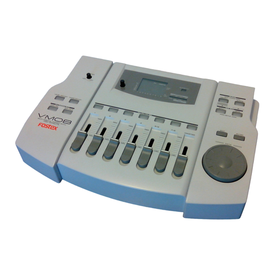
Owner's Manual
Model
Eight Channel Digital Mixer with DSP Effects
Introduction
Thank you very much for purchasing the Fostex VM08.
The VM08 digital mini-mixer does all internal signal processing digitally.
The input section consists of eight analog input channels including four for
microphones. The output section, in addition to normal analog outputs such
as two channel stereo and a headphone output, also has S/P DIF digital opti-
cal output with a 44.1 kHz sampling frequency: and 20 bit quantization.
The internal buss is two channel stereo L/R, plus an independent Effects buss
(1, 2) and an AUX buss (1, 2).
In addition to each input channel, an EQ is also provided for the master out-
put. The VM08 also incorporates high performance DSP multi-effects on two
channels that operate by A.S.P. (Fostex Advanced Signal Processing Technol-
ogy*) exclusively developed by Fostex. This allows a wide range of equalizing
and effects processing. All settings, including mix and effects settings, are
stored in scene memory, and a desired scene memory can be recalled instan-
taneously. Although small and lightweight, the VM08 is a high performance
unit. Please read this manual carefully before operation to understand all
functions of the VM08.
* See page 18 for more details on the A.S.P. (Fostex Advanced Signal Process-
ing Technology).
Advertisement
Table of Contents

Related Manuals for Fostex VM08


Summary of Contents for Fostex VM08
- Page 1 Although small and lightweight, the VM08 is a high performance unit. Please read this manual carefully before operation to understand all functions of the VM08. * See page 18 for more details on the A.S.P. (Fostex Advanced Signal Process- ing Technology).
-
Page 2: Safety Instructions
Model VM08 Owner’s Manual CAUTION RISK OF ELECTRIC SHOCK DO NOT OPEN CAUTION: TO REDUCE THE RISK OF ELECTRIC SHOCK, DO NOT REMOVE COVER (OR BACK). NO USER - SERVICEABLE PARTS INSIDE. REFER SERVICING TO QUALIFIED SERVICE PERSONNEL. "WARNING" "TO REDUCE THE RISK OF FIRE OR ELECTRIC SHOCK, DO NOT EXPOSE THIS APPLIANCE TO RAIN OR MOISTURE."... -
Page 3: Table Of Contents
These things may cause electric shock or short circuit the VM08, and damage it. If the VM08 should become wet, unplug the AC adaptor from the AC outlet, and contact your authorized service station. -
Page 4: Names And Functions
FOOT SW AUX SEND 10 11 4. RESET switch This switch resets the CPU inside VM08. Refer to page 6 for details. 5. AUX send jack AUX SEND level signals, adjusted in the channel parameter edit mode, are output here. Refer to pages 8 and 17 for details. - Page 5 11. LCD display Various figures are displayed here. Refer to [Ini- tial state of VM08] in page 11 for details. 12. Scene number display The current scene number is displayed here. Refer to [Scene memory mode] on page 24 for de- tails.
-
Page 6: Before Operation
It is possible for the computer to malfunction at power ON/OFF or by electro induction noise from light- ning. In this happens, switch the power ON/OFF to the VM08 several times. If it does not return to normal operation, press the rear panel [RESET] switch with a slender ball point pen or similar tool. This returns all settings to the initial figures setup at shipping from the plant. -
Page 7: Peripheral Equipment Connection
As shown in the schematic, both stereo and mono output sound sources can be connected. For either type signals, the input mode can be selected using the VM08’s setup mode. Refer to [Setup mode] on page 27 for setup of the input mode. Refer to next page for details in preparing and wiring the TRS phone plug. - Page 8 AC wall outlet. Since the VM08 does not have a power switch, ON/OFF of power is done by plugging and unplugging the AC adaptor from the AC wall outlet. If you don’t plan on using the VM08 for some length of time, the AC adaptor must be unplugged from the AC wall outlet.
-
Page 9: Application Examples
The following are actual examples in application of VM08 and could be helpful in your applica- tion. <Example-1> : To expand the FD-8 analog simultaneous recording channel The FD-8 analog simultaneous recording track can be extended to "4" by connecting the FD-8 DATA IN jack to the VM08 S/P DIF OUT jack. - Page 10 Model VM08 Owner’s Manual <Example-5> : For one take live studio recording You can use the VM08 to send the mixed digital audio via S/P DIF to a DAT or PC with Digital In. You can also add the internal digital effect when mixing audio.
-
Page 11: Initial State Of The Vm08
[20] but the preset scene [00] cannot be changed. Refer to page 24 for details on the scene memory. * If, for some reason, you would like to return the VM08 setting to the factory default figure, refer to [Reset of VM08] on page 6. -
Page 12: Normal Mix Mode
When the VM08 is in [Initial state of VM08], as explained in the previous section, if the INPUT fader of the channel to which a signal is being input (Example: The channel 1 INPUT fader if a sound source is connected to INPUT 1.) and the MASTER fader is raised, signals will be output from the rear panel STEREO... - Page 13 [Fader adjust mode] explanation. * To set to the present fader position: Press the flashing LEVEL ADJUST key and the VM08 will enter the level adjust mode. Then setup by following [Level adjust mode] on page 27.
-
Page 14: Channel Parameter Edit Mode
Twelve items, as shown in list below, can be set by the channel parameter edit mode. Regard- less of the VM08’s current mode, their respective edit modes can be entered by executing the key operations listed below. To exit from the channel parameter edit mode, press the EXIT key. -
Page 15: Eq Setup Method
The VM08 is set to POST (post fader) in the initial state. <Useful information!> * The EFFECT SEND signal adjusted in channels 1 ~ 4, 5/6 and 7/8 is sent to the VM08 internal DSP multi-effects (EFF1 or EFF 2). The operating explanation used here is based on the effects type ([Norm. -
Page 16: Setup Method Of The Aux Send Level
AUX SEND jack. The same as with the EFFECT SEND signal, either POST or PRE can be selected for the AUX SEND signal. The VM08 is set to POST in the initial state. To change the setting, please see below [Setup of PRE/POST]. -
Page 17: Pre/Post Setup Method
Blinking 2. Press the desired CH ON/CH SEL key and select the channel you wish to adjust. Model VM08 Owner’s Manual 3. Adjust the number with the DATA encoder. [Pre] or [Post] can be selected. The graphic display will also change at the same time. -
Page 18: Effect Edit Mode
Model VM08 Owner’s Manual The VM08 offers high quality ambient effects by employing the A. S. P. (Fostex Advanced Signal Processing Technology), which is exclusively developed by Fostex. With the A. S. P., you can obtain an incomparably clean and high density Hall Reverb, overwhelmingly clear Room Re- verb and wonderfully hi-fidelity Plate Reverb. -
Page 19: About The Effect Types
About the effect types The VM08 contains two independent DSP multi-effect units; EFF 1 and EFF 2. A variety of effect types are preset for each effect unit. By selecting a suitable effect type, you can process the sound as you wish. You can also edit the parameters of the selected effect type to create your own effect sounds. -
Page 20: Selecting The Effect Type
Model VM08 Owner’s Manual Effect types preset for EFF 2 Name Parameter type 1--28 are the same effect types as the EFF 1 presets listed on the preceding page. (For details refer to the preceding page.) MonoDELAY DELAY PanDELAY DELAY... -
Page 21: Effect Parameter Settings
The foot switch can be used to switch muting on/off for effect 1 or effect 2, or can simultaneously mute both effect 1 and effect 2. For details refer to p.27 "Setup mode." Model VM08 Owner’s Manual Details on the parameters are given lowing section, "Parameter settings."... -
Page 22: Effect Parameter Details
Model VM08 Owner’s Manual Effect parameter details The parameters that can be adjusted will depend on the parameter type. Reverb effect parameters (parameter type: REVERB) For effect types 1--24 of the preceding "Effect type" table, the following four parameters can be ad- justed. - Page 23 Make fine adjustments to the amount of pitch shift. Range: -50--0--+50 (101 steps in increments of 1) * +50 is a semitone sharp. -50 is a semitone flat. 3. MODE Select the processing method. Range: 1--3 (3 steps) Model VM08 Owner’s Manual...
-
Page 24: Scene Memory Mode
Model VM08 Owner’s Manual The VM08 provides 21 scene memories (scene numbers 00--20). Of these, scene number [00] is a preset scene named "Initial Mix," and cannot be modified by the user. Your own settings can be stored in scene numbers [01]--[20]. Each scene stores the contents of Normal Mix mode, Channel Parameter Edit mode, and Effect Edit mode as a set. -
Page 25: Level Adjust
Fader Adjust will function in Normal Mix mode as well as after a scene is recalled. In Normal Mix mode, the FADER ADJUST key / LEVEL ADJUST key will blink to indicate that the fader locations before the VM08's power is turned off are different than the fader locations when the power was turned on. -
Page 26: Directly Recalling A Scene Memory
Model VM08 Owner’s Manual Directly recalling a scene memory In addition to the method described earlier in "Scene recall," a scene memory can also be recalled directly using the following method of stepping consecutively through the stored scenes. < Note >... -
Page 27: Setup Mode
In Setup mode you can make the following settings to specify how the VM08 will operate. 1. INPUT 5/6 setting (specify INPUT 5/6 as stereo or mono input) 2. INPUT 7/8 setting (specify INPUT 7/8 as stereo or mono input) 3. -
Page 28: Fader Fix Setting
[Batt Empty] will appear in the display when the VM08 is powered-on. It is not possible for the user to replace the internal battery. Please contact a nearby Fostex office or service station. -
Page 29: Specifications
CH 3 CH 4 METER INPUT 5/6 100Hz 1kHz 10kHz (-6dBV) MONO/STEREO CH5/6 CH7/8 Model VM08 Owner’s Manual Specifications <FOOT SWITCH> Connector <OTHERS> Equalizer Frequency response : 20Hz ~ 20kHz (TYPICAL) Dynamic range Sampling frequency : 44.1kHz Total harmonic distortion Crosstalk <GENERAL:>... -
Page 30: The Affect Of Immunity On This Equipment
In the electrical fast transient / burst requirements, radiated electromagnetic field requirements and static electricity discharging environment, this could be affected by generation of noise in some cases. Fostex Distributors List In Europe * Including non - EU countries. * underlined: contracted distributors (as of April, 1999) <AUSTRIA>...
Need help?
Do you have a question about the VM08 and is the answer not in the manual?
Questions and answers