Table of Contents
Advertisement
Advertisement
Table of Contents

Related Manuals for BayTech ATS Series

Summary of Contents for BayTech ATS Series
- Page 1 2019 Transfer Switch (ATS) COPYRIGHT 2019 Bay Technical Associates, Inc. 1/1/2019 ...
-
Page 2: Table Of Contents
Default Set Points ............................19 Frequency Set ..............................19 Voltage Set ..............................20 LOSSPSP ............................... 20 RESET PROCEDURE ............................20 BAYTECH PRODUCT (US) WARRANTY ......................21 Exceptions ............................... 21 BayTech Extended Warranty .......................... 21 Technical Support ............................22 Repair Policy ..............................22 ... - Page 3 If you have any problems with your installation, please contact a BayTech Applications Engineer at 228-563-7334, or toll free from anywhere in the United States using 1-800-523-2702 or contact us at our Web Site, www.baytech.net.
-
Page 4: Compliance Standard
NOTE: Custom cables are available to connect a device to this unit’s serial port. These custom cables are one-way cables labeled with Baytech on one end and a device name on the other end. REMARQUE: les câbles sur mesure sont disponibles pour connecter un périphérique au port série de cet appareil. -
Page 5: Installation
Inspect equipment carefully for damage that may have occurred in shipment. If there is damage to the equipment or if materials are missing, contact BayTech technical support at 228-563- 7334 or call toll free inside the United States at 800-523-2702. At a minimum, you should receive the following: 1. - Page 6 230V/16A Rated Model: (20A Maximum Over current protection Device) NOTE: due to the 4-relay design the current ATS series permits the input sources to be out of phase for normal operation. NOTE: en raison de la conception 4-relais de la série actuelle ATS permet aux sources d'entrée d'être hors de phase pour un fonctionnement normal.
-
Page 7: Circuit Breaker
Receive (Data In) No Connection. Signal Ground DCD into the ATS. Adapter signals Listed are the pin specifications for the BayTech cable and adapters and the terminal COM ports: Figure 1: Serial Port Pin Out Signal RS-232 RS-232 COM Port... -
Page 8: Adapters
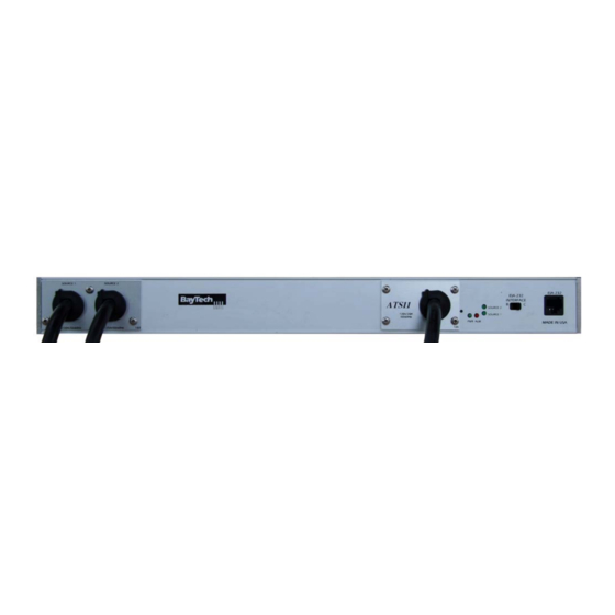
RJ08X007 Standard Rollover Cable RJ45 to RJ45 Figure 2: RJ08X007 Pin Out Figure 3: RJ45 Connector & Plug Adapters Figure 4: 9FRJ45PC Cisco Adapter Pin Out Figure 5: 9FRJ45PC-1 Adaptor Pin Out (Use with RJ08X007 Cable And B/C switch in “C”) (Use with RJ08X007 Cable And B/C switch in “B”) - Page 9 ATS11 Front, ATS22 similar Front ATS11/ATS22 Rear ATS12 Rear on Top, Front on Bottom ATS23 similar Rear but UL489 Breakers on Front panel ATS11 and 12 same dimensions Rear Switch & Indicators: EIA232 INTERFACE B/C = Set switch to ‘B’ for normal operations. ‘C’ changes the pin out to allow for Cisco’s PC cable to operate in most cases but not all.
-
Page 10: Main Control
5. You should get a Status menu similar to the one seen below. ATS Series (C) 2014 Baytech F1.18 Option(s) Installed: True RMS Voltage True RMS Current Internal Temperature Unit ID: ATS Series Primary Source 1 Source 2: 121.2 Volts ------------------------------------------------------------------------------ Power True RMS Peak RMS True RMS... - Page 11 The Status Menu will display after the user logs in (if a login is required). This menu lists the firmware version, installed options, primary source, secondary source voltage, primary source current, voltage, and power, and the internal temperature of the ATS unit. ATS Series If there are users installed on the unit a login (C) 2014 BayTech will be required.
-
Page 12: Help Options
HELP OPTIONS Menu 1: Help ATS> help Status <cr> --ATS-11 Status Config <cr> --Enter configuration mode Current <cr> --Display True RMS Current Voltage <cr> --Display True RMS Voltage Clear <cr> --Reset the maximum detected current Temp <cr> --Read current temperature Logout <cr> --Logoff Logoff <cr>... -
Page 13: Delete A User
Select A), to add a user. The unit will ---------------------- User prompt for a user name. | 1 | ---------------------- 1)...Dave | N | Type the user name and press ‘Enter’. ---------------------- A)...Add User NOTE: User name is case sensitive. The unit D)...Delete User R)...Rename User will display the User Menu with the added user... -
Page 14: Assigned Outlets
Assigned Outlets ---------------------- The Assigned Outlet Menu displays the outlets a user can access. User Select a user number from the Managed User Menu, the unit will | 1| ---------------------- display the Assign Outlet Menu Dave | N| ---------------------- 1)...Add Outlet(s) 2)...Remove Outlet(s) 3)...Add All Outlets 4)...Remove All Outlets... -
Page 15: Change Unit Id
Change Unit ID Enter Request: 4 Select 4), from the Configure Menu allows the ‘admin’ user to change the unit ID. Default is Blank. The unit displays the following: Current Unit ID: ATS12 Modify (Y/N)? y Enter New Unit ID:ATS12 East Unit ID: ATS12 East Change Alarm Threshold Enter Request: 5... -
Page 16: Change Ats Delay Switch To Secondary
Change ATS Delay Switch to Secondary Select 8), from the configure menu to allow the user to set the delay time the unit switches to the Secondary Input once the Primary input drops below the Loss of Power Threshold. Default is Disabled, and Default time is 0-seconds. -
Page 17: Change Buzzer Audible Alarms
Change Buzzer Audible Alarms Select 9), from the configure menu to allow the user to turn off the Alarm for a Power Loss and Over-Current Alarm. Power Loss Buzzer Alarm Default is Disabled. Over-Current Buzzer Alarm Default is Enabled. 1)...Power loss buzzer alarm: Off Default off 2)...Over current buzzer alarm: On ... -
Page 18: Display Current Electrical Characteristics
Display Current Electrical Characteristics: Type Current at the prompt to show the unit’s True ------------------------------------------ Circuit True RMS Peak RMS RMS Current and Peak RMS Current and the unit will Group Current Current display the following: ------------------------------------------ Circuit C1 0.0 Amps 0.7 Amps Circuit C2 0.0 Amps... -
Page 19: Identify Current User
Identify Current User Type Whoami at the prompt to determine the current user, the unit will display the Current User: root following: To change the user, logout of the unit and log back in using the new user name. Unit Identification Type Unitid at the prompt to determine the Unit ID, the unit will display the following: Unit ID: ATS18 To change the unit ID, Go to the Outlet Configuration menu and select “Change Unit... -
Page 20: Voltage Set
Voltage Set Current operating voltage is: 208.0 Volts The menu displays the current operating voltage and then asks Enter operating voltage the operator to choose the new operating voltage. If no change is 1)...100 Volts 2)...110 Volts required press “Enter”, otherwise select the appropriate number. 3)...120 Volts Type “X”... -
Page 21: Baytech Product (Us) Warranty
BayTech. BayTech will pay return costs for delivery within the Continental United States. All repair and return shipments must be approved by BayTech and must be accompanied by an RA (return authorization) number. Please refer to our Repair and Return Policy below. -
Page 22: Technical Support
Determination of credit amount will be made after BayTech receives the product. Returns on BayTech products older than 3 months are subject to a 15% re-stocking fee of the list price of the product and will be evaluated on a case-by-case basis. BayTech does not allow returns on products out of warranty or for any type of custom product. -
Page 23: Return Authorization Process
Return Authorization Process 1. Contact BayTech to get a Return Authorization (RA) Number. IMPORTANT: BayTech will not accept any returns without an RA number. 2. Package the unit carefully in its original packaging or similar packaging. The warranty does not cover damage sustained during shipment. -
Page 24: Troubleshooting
TROUBLESHOOTING Problem: Solution: Reference: Unit Switches Continuously Verify the voltage and frequency is set Page 17 for the input voltage via ATSSET command Unit has long beep and long The beeping signifies NO VOLTAGE This is normal operation. No means pauses continuously, Part 1 from one input, Connect both inputs to of silencing beeping... -
Page 25: Bracket Installation
Bracket Installation HORIZONTAL Mounts: Each horizontal, Baytech unit is shipped with a set of horizontal brackets, and four screws packaged in a bubble-wrap bag. 1U Bracket, part number: M140R115 Attach brackets to the each of the unit’s side panel with two screws. Verify both brackets are facing the same direction on the unit, once attached.
Need help?
Do you have a question about the ATS Series and is the answer not in the manual?
Questions and answers