
Related Manuals for Kent Scientific PhysioSuite


Summary of Contents for Kent Scientific PhysioSuite
- Page 1 PhysioSuite ® Modular System Fully integrated touch screen control and display User’s Guide...
- Page 2 PhysioSuite ® Modular System Fully integrated touch screen control and display User’s Guide Technical Help: 860-626-1172 ©2019 Kent Scientific Corporation, Documentation Version 2.0 for On-Unit Help Version 5.03 and Firmware Revision 2.00.00-60 August 2019...
-
Page 3: Table Of Contents
TABLE OF CONTENTS Introduction System Components ..............1 Navigating PhysioSuite® ............. 2 System Customization Custom Run Screen ..............3 Alarms .....................4 RoVent® Automatic Ventilator Set Up Hardware ................6 Initial Set-Up ................. 7 Configure Settings ............... 8 Procedure for Use ..............10 Constant Flow Mode .............. - Page 4 CapnoScan® End-Tidal CO2 Monitor Set Up Hardware .................17 Initial Set-Up ................19 Procedure for Use ..............19 Troubleshooting ................ 20 CapnoScan Sensor Maintenance ........... 20 RightTemp® Temperature Monitor and Homeothermic Warming Set Up Hardware .................21 Initial Set-Up ................22 Procedure For Use ..............23 Troubleshooting .................23 RightTemp Pad and Sensor Maintenance ......24 Data Management...
-
Page 5: Introduction
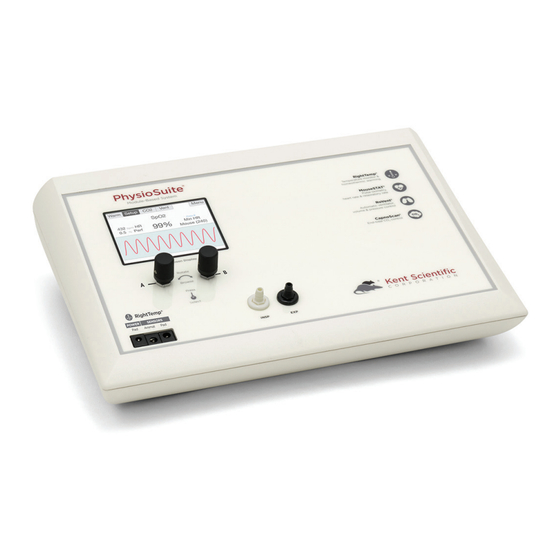
The PhysioSuite is not designed, intended or authorized for use in human applications. System Components Front Panel Note: If your PhysioSuite was purchased with RoVent, it will contain four airflow ports. If it was not purchased with RoVent, these ports will be absent from the controller. Back Panel... -
Page 6: Navigating Physiosuite
Navigating PhysioSuite® Module Screens The PhysioSuite Run screen has a designated screen for each installed module. Touch the tabs along the top of the screen to view the parameters and important settings for each module. Touch the tab again to open the module’s extended Setup Menu. -
Page 7: System Customization
System Customization Custom Run Screen PhysioSuite allows you to configure your own Run Screen, allowing a combination of parameters from any installed modules to appear on a single screen. When using a Custom Run Screen, all settings need to be entered from the Menu or configured with Dial A and B. -
Page 8: Alarms
2. Turn the Dial to increase or decrease the value for the assigned setting. After 3 seconds, the PhysioSuite beeps again and the command text returns to black. As you turn a Dial, setting changes takes place immediately. Alarms The PhysioSuite Alarms alert you to certain conditions that might require attention. - Page 9 2) Touch Data Mgmt, then Alarms. Silence all Alarms If you do not wish for the PhysioSuite to make an audible tone when an alarm is triggered, you can create silent alarms. Turn Dial B to choose “Silence all Alarms” or “Allow Sound”.
-
Page 10: Set Up Hardware
If ventilating using an anesthetic gas vaporizer or compressed gas source: 1. Connect the Bypass Assembly to the rear ports of the PhysioSuite. Note: The PhysioSuite RoVent is designed to operate with the ports at neutral pressure. The Bypass Assembly is required to neutralize any pressure buildup in the rear tubing. -
Page 11: Initial Set-Up
1. Measure Deadspace The Deadspace calibration will measure the volume of tubing between the PhysioSuite RoVent module and the animal. It is important that the Deadspace is recalibrated every time the tubing configuration is changed to maintain accurate tidal volume delivery. -
Page 12: Configure Settings
The first time the RoVent is used, or any time the accessories have changed, be sure to perform a Deadspace Calibration and verify the ventilator settings. Note: Never perform these functions when an animal is connected to the ventilator. 2. Zero Sensors Zeroing the sensors ensures that the internal pressure and flow sensors are working properly, and calibrates them prior to the ventilation. - Page 13 The Vent Setup also allows you to make advanced ventilation settings: • PEEP: Automatically add a positive end-expiratory pressure. o Choose between 0cmH2O and 9cmH2O. o Used to prevent alveolar collapse during open-chest procedures. • Sigh Breath: Automatically add an intermittent breath with a larger tidal volume. o Choose frequency and tidal volume of sigh breaths.
-
Page 14: Procedure For Use
1. From the Vent Run Screen, touch Setup, then More Ventilator. 2. Touch Triggers Menu. 3. Turn Dial B to choose an action. Some actions will require additional settings. Please contact Kent Scientific if you need assistance in enabling a trigger function. -
Page 15: Constant Flow Mode
Constant Flow Mode For setups where a constant flow or gas passthrough is required, the RoVent can be set to Air Mode. To access Air Mode, touch the Air menu. Air Mode contains three different flow options: 1. Body Weight Flow: Preset based on the Body Weight setting 2. -
Page 16: Troubleshooting
RoVent Troubleshooting Alarm Messages Message Definition Solution Tube open to The highest measured • Check the tubing between the INS and pressure in a breath cycle EXP ports for leaks or loose connections. atmosphere is under 25% of the target •... - Page 17 Kent Scientific. connection or a crack or hole in the tubing. There is an internal Retest making sure that the tubing is not flexed or Low baffle RoVent problem. moved. If the error recurs, contact Kent Scientific. pressure or Baffle leaks...
-
Page 18: Set Up Hardware
Heart Rate Monitor Set Up Hardware Sensor: 1. Connect the interface cable to the MouseSTAT port on the back of the PhysioSuite. 2. Connect the sensor to the interface cable and ensure that the connection is secure. The MouseSTAT Run Screen:... -
Page 19: Procedure For Use
Procedure for Use 1) Anesthetize the animal and place on the RightTemp warming pad. Tip: Kent Scientific recommends the use of inhalant anesthetics. Injectable anesthetic agents have a greater effect on circulation, making pulse oximetry challenging. Always warm the animal to support circulation in the animal’s extremities. -
Page 20: Troubleshooting
MouseSTAT Troubleshooting Problem Possible Cause Solutions There is no red light Sensor not fully connected • Ensure that all connections are tight, especially at the back of the controller. blinking light in the sensor. Damaged wire in sensor or • Replace the damaged cable. -
Page 21: Set Up Hardware
The CO2 Run Screen Set Up Hardware Sensor: 1. Connect: 1) the interface cable to the CapnoScan port on the back of the PhysioSuite 2) the side-stream sensor to the interface cable, ensuring that the connection is secure. 2. Insert: 1) the sampling assembly into the back slot of the side stream unit. - Page 22 PhysioSuite Ventilator and CapnoScan Setup PhysioSuite CapnoScan with External Ventilator Setup...
-
Page 23: Initial Set-Up
Percent NO2: Set the concentration of NO2 in the balance gas. Note: Whenever these settings are changed, disconnect the CapnoScan from the PhysioSuite, then reconnect it. This will reinitialize the sensor so that the new settings take effect. 3) Connect the animal to the ventilator. -
Page 24: Troubleshooting
CapnoScan not running or • Ensure that all connections are tight, readings. not connected especially at the back of the PhysioSuite. • Ensure that the CapnoScan is running. Sampling tube dirty or • Ensure that the sampling tube is not wet, damaged soiled or damaged. -
Page 25: Set Up Hardware
RightTemp Temperature Monitor and Homeothermic Warming Set Up Hardware 1. Connect the warming pad to the Pad Power port on the front of the PhysioSuite. 2. Choose one probe as the body temperature sensor, and the other as the pad temperature sensor. -
Page 26: Initial Set-Up
Initial Set-Up 1) From the Warm Run Screen, touch Setup. 2) Touch Control Warming, and choose the warming method. • Off: temperature monitoring, no warming • Warming Pad: temperature monitoring with power adjustment • Homeothermic: temperature monitoring and control using animal sensor control Pad Temperature Regulation: Pad temperature regulation allows you to set and monitor the temperature of the warm-... -
Page 27: Procedure For Use
Incorrect sensor placement • Place pad sensors directly beneath the animal. • Place animal sensor rectally only. “Lost Sensor” alarm The sensor has been • Reconnect the temperature sensors. disconnected. Sensor failure • Contact Kent Scientific for assistance. -
Page 28: Righttemp Pad And Sensor Maintenance
RightTemp Pad and Sensor Maintenance • Use the disposable warming pad covers to prevent soiling the warming pad. • Wipe the warming pad clean with a damp cloth if needed. Never saturate the warming pad. • Gently wipe the sensors clean between uses. -
Page 29: Data Management
Data Management For PC Connections Kent Scientific devices can collect and monitor data using a serial over-USB connection. The data can be uploaded to a variety of programs, including ADI’s data acquisition software, LabChart®. If you do not have LabChart, please contact Kent Scientific for recommended alternatives. -
Page 30: History
2. From any Run Screen, Touch: 1) Menu, then Data Management, then Upload 3. Choose: 1) The Parameters to upload 2) The timing 3.) Then touch Enable. The “Always enabled” setting saves data as long as the controller is on. The “Enabled while running” setting is available only if your system contains a RoVent ventilator, and saves data only when the ventilator is running. -
Page 31: Analog Output
2) Send All: export all History saved to the device. Analog The Analog Output feature sends an analog signal corresponding to a single Parameter to external equipment via a remote cable. Please contact Kent Scientific for a remote cable if you would like to use this feature. - Page 32 To configure Analog Output 1. From any Run Screen, Touch: 2. Menu, then Data Management, then Analog Output. 3. Choose a Parameter to output. The voltage output ranges from 0-3V, with 0V assigned to the low limit of the range, and 3V to the high limit. See Custom Run Screen on page 3 to set a Range corresponding to the 0-3V output.
-
Page 33: General Information
General Information Thank you for purchasing a PhysioSuite. We truly appreciate your business. We strongly advise that you read and study this User’s Guide to fully appreciate all the features, benefits, and capa- bilities of the PhysioSuite. Contact Information Kent Scientific Corporation... -
Page 34: Satisfaction Guarantee
Prior to shipment, please clean and decontaminate the product of any chemical, biological, or isotopic contamination. Please include a completed Product Return Form with the shipment. This form can be obtained by contacting Kent Scientific Customer Service at 888-572-8887 or 860-626-1172. - Page 35 RoVent Volume controlled, pressure controlled Control Modes I:E Ratio 1:1 to 1:5 PEEP Built-in Automatic or Manual Respiratory Assist Sigh Pressure 2cmH2O to 30cmH2O Sigh Breath Automatic or Manual Respiratory Rate Range 20bpm to 400bpm Tidal Volume Range 0.01 to 12.0mL Weight Range 3g to 1,250g MouseSTAT...
- Page 36 Operating: 0°C to 45°C, 10% to 90% RH, non-condensing Storage: -40°C to 70°C, <90% RH, non-condensing SomnoSuite, RoVent, CapnoScan, MouseSTAT and RightTemp are registered trademarks of Kent Scientific Corporation. Windows is a registered trademark of Microsoft Corporation. LabChart is a registered trademark of ADInstruments Pty Ltd.
-
Page 37: Index
Index air flow ........1, 10, 12 compensation .......19 internal storage ......25 alarms ........4, 5, 30 com port ........ 24, 26 kent device ......24, 26 always enabled ......25 compressed gas ......6 leak test ........11, 12 analog .........3, 26, 27 config ........ - Page 38 percent no ........18 side-stream ........16 percent O ........18 sigh breath ......9, 30 port ....... 1, 6, 11, 13, 16, 19, specifications ......29, 31 20, 24-26 target pressure ......8-10 positive end-expiratory pressure ........... 9 target temperatures ....22 pressure .....6, 8-12, 18, 30, 31 temperature sensor ..20, 21, 30 probe........
- Page 39 1116 Litchfield Street Torrington, Connecticut 06790 Local: 860-626-1172 Toll-Free: 888-572-8887...
Need help?
Do you have a question about the PhysioSuite and is the answer not in the manual?
Questions and answers