Table of Contents
Advertisement
Advertisement
Table of Contents

Related Manuals for Unical XC-K Series


Summary of Contents for Unical XC-K Series
- Page 1 XC-K INSTALLATION AND MAINTENANCE 44879 - 03/12 INSTRUCTIONS rev. 0...
-
Page 2: Table Of Contents
General information TABLE OF CONTENTS 1 GENERAL INFORMATION ....................................3 1.1 Symbols used in the manual ..................................3 1.2 Appropriate use of appliance ..................................3 1.3 Water treatment ......................................3 1.4 Information for user or system manager ..............................3 1.5 Safety warnings ......................................4 1.6 Technical data plate ...................................... -
Page 3: General Information
The appliance is intended to operate in hot air circulation heating systems. Any other use must be considered improper. UNICAL shall not held be liable for any damage resulting from improper use; in this case the user is fully responsible for the risk. -
Page 4: Safety Warnings
General Information 1.5 - SAFETY WARNINGS Attentione! The appliance must be installed, adjusted and maintained by professionally qualified personnel, in compliance with standards and provisions in force. Incorrect installation can cause damage to persons, animals and objects for which the manufacturer cannot be held responsible. DANGER! NEVER attempt performing maintenance or repairs on the boiler on your own initiative. -
Page 5: Technical Data Plate
(80°C - 60°C) kW (50°C - 30°C) Useful gas output Useful diesel output Furnace P.I. No. Approvals For serial No. see boiler body 46033 CASTELDARIO (MN) - Via Roma tel. 0376 57001 - fax 0376 660556 AG S.P.A. www.unical.eu info@unical-ag.com... -
Page 6: General Warnings
Any repairs must be performed solely by personnel authorised and maintenance safety. by Unical using original spare parts only. Failure to comply with the above can jeopardise the safety of the appliance. Keep the booklet with care for further consultation. -
Page 7: Technical Features And Dimensions
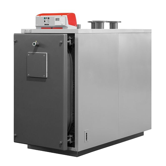
Technical features and dimensions TECHNICAL FEATURES AND DIMENSIONS 2.1 - TECHNICAL FEATURES The XC-K boilers are made up of an external shell which houses each). The shell has holes at the sides for the cable glands of the the completely wet blind cylindrical furnace, where the first two combustion gas passes are completed, and by a special power, pumps, burner cables and those of any other auxiliary tube and shell, used for the third pass. -
Page 8: Dimensions
Technical features and dimensions 2.3 - DIMENSIONS XC-K 124 3° fig. 2 T3 High temperature C.H. return T7 Chimney connection 1 Panel board T4 Expansion vessel connection T8 Condensation drain 2 Flame sight glass T5 Boiler drain T1 C.H. flow T6 Burner connection T2 Low temperature C.H. - Page 9 Technical features and dimensions XC-K 200÷570 T2 - T1 - T4 T2 - T3 3° fig. 4 T3 High temperature C.H. return T7 Chimney connection 1 Panel board T4 Expansion vessel connection T8 Condensation drain 2 Flame sight glass T5 Boiler drain T1 C.H.
- Page 10 Technical features and dimensions XC-K 700÷2160 T2 - T1 - T4 T2 - T3 3° fig. 8 T3 High temperature C.H. return T7 Chimney connection 1 Panel board T4 Expansion vessel connection T8 Condensation drain 2 Flame sight glass T1 C.H. flow T5 Boiler drain T2 Low temperature C.H.
-
Page 11: Operating Data
2.4 - OPERATING DATA XC-K 124 XC-K 200 XC-K 290 XC-K 400 XC-K 480 XC-K 570 XC-K 700 XC-K 900 GAS-FIRED 112,8 182,7 265,6 367,1 440,7 523,3 642,6 826,2 Nominal heat output (80°-60°C) Nominal heat output (50°-30°C) 115,9 186,9 373,8 448,6 532,7 654,2... -
Page 12: Installation Instructions
Installation instructions INSTALLATION INSTRUCTIONS 3.1 - GENERAL WARNINGS ATTENTION! In rooms with the presence of aggressive vapours or dust, the appliance must operate ATTENTION! independently from the air inside the This boiler is intended solely for the use for installation room! which it was expressly designed. -
Page 13: Installation Standards
Installation instructions 3.2 - INSTALLATION STANDARDS The appliance must be installed in compliance with the instructions provided in this manual. It must be installed by a professionally qualified technician, who shall assume the responsibility of respecting all local and/or national laws published in the official journal, as well as applicable technical standards. -
Page 14: Handling
Installation instructions 3.3 - HANDLING The boiler can be handled easily, lifting it by means If necessary for clearance purposes, the door and the smoke of upper hooks or shifting it on rollers underneath chamber can be removed to make it easier to enter the boiler the sturdy base longerons. -
Page 15: Installing The Burner
Installation instructions especially those approved based on the standards indicated above. Further information is provided in the chapter “Commissioning”. øA BOILER TYPE XC-K 124 XC-K 200 XC-K 290 ÷ XC-K 400 fig. 12 XC-K 480 ÷ XC-K 570 DIMENSIONS OF BURNER BLAST TUBE XC-K 700 ÷... -
Page 16: Furnace Door Adjustment, Opening And Closing
Installation instructions 3.7 - FURNACE DOOR: ADJUSTMENT, OPENING AND CLOSING 3.7.1 - “XC-K 124 ÷ XC-K 900” BOILERS For all these models, the door is hinged and fixed according to the layout in fig. 14. In these cases, the door is mounted with four equal hinges: the two on the left side are normally used as rotation hinges (from right to left), while the two on the right side are used as... -
Page 17: Xc-K 1820÷Xc-K 2160 Boilers
Installation instructions 3.7.3 - “XC-K 1820 ÷ XC-K 2160” BOILERS For all these models, the door is hinged and fixed according to the layout in fig. 16. In these cases, the two hinges on the left are normally used as rotation hinges (from right to left), while the two on the right side are used as closing hinges. -
Page 18: Connecting Flue Exhaust Pipe
Installation instructions 3.8 - CONNECTING FLUE EXHAUST PIPE To connect the flue gas exhaust pipe, local and national The supplier will have no contractual or extra- standards must be respected. contractual liability for damage caused due to The XC-K boiler can be attached to the chimney in different incorrect installation and use and anyway failure ways;... -
Page 19: Xc-K 1140÷Xc-K 1420 Boilers
1 bar. Unical will not be held liable for damage to close the filling tap and bleed air once again through the persons, animals or objects due to failure radiator air release valves. -
Page 20: Connecting Gas
Installation instructions NOTE ATTENTION! The water pressure in the heating system must After removing the protective screw, a small not be drop below 1 bar; open the filling tap when amount of water could leak out. pressure is too low. Dry off all wet surfaces before powering the boiler. -
Page 21: Packaging
The panel and accessories are inside the combustion chamber. Unical will not be held liable for damage to Before starting installation, make sure that the length and width persons, animals or objects due to failure to of the boiler body received correspond respectively to the comply with the instruction above. -
Page 22: Assembling Casing
Installation instructions 3.14 - ASSEMBLING CASING XC-K 124 fig. 18 7 12 Assembly sequence (Ref. fig. 18, 21) A) Mount the insulation jackets (pos. 1 and 2) of the boiler Fit the panel board to the upper panel (pos. 9). body and secure the 2 edges with the elastic straps Fit the upper panel (pos. - Page 23 Installation instructions XC-K 200÷XC-K 1140 fig. 19 Assembly sequence (Ref. fig. 19, 21) G) Insert into the conduits the bulbs of the instruments as A) Mount the insulation jackets (pos. 1 and 2) of the boiler body indicated in fig. 21 and, depending on the panel board and secure the 2 edges with the elastic straps (pos.
-
Page 24: Electrical Connections
Installation instructions XC-K 1420÷XC-K 2160 fig. 20 Assembly sequence (Ref. fig. 20, 21) indicated in fig. 21 and, depending on the panel board A) Mount the insulation jackets (pos. 1 and 2) of the boiler body installed on the boiler, the probes as illustrated in the electric- and secure the 2 edges with the elastic straps (pos. - Page 25 Installation instructions 1 Thermometer probe (where included) 2 Working thermostat probe 3 Contact spring 4 Safety spring 5 Safety thermostat probe fig. 21 3.15 - ELECTRICAL CONNECTIONS 230V electric power supply connection The electrical connections are illustrated in chapters 3.16, 3.17, General warnings 3.18, 3.19 and 3.21 for modulating burners and chapters 3.22, 3.23, 3.24, 3.25 and 3.27 for dual-stage burners.
-
Page 26: Modulating Master Panel Board Code 37892
Installation instructions 3.16 - MODULATING MASTER PANEL BOARD code 37892 The main switch 14 powers the board and the equipment connected to it. The switches 18 and 19 control the burner and P1 pump if the boiler operates in cascade. The switches 20 and 21 control the Z1 pump (direct) and Z2 pump (mixed). - Page 27 Installation instructions PARAMETERS PROGRAMMABLE BY TECHNICIAN AND PROTECTED BY ACCESS CODE FOR HEATING CONTROLLER type E8.5064 INSTALLATION Description Value range Default Individual values CODE NUMBER 0000 - 9999 ENTRY CODE NUMBER (adjustment) 0000 0000 - 9999 BOILER BUS ID .., 01 - 08 ---- BUS ID 1 1 1 1 1 (00), 01 - 015...
- Page 28 Installation instructions Description Value range Default Individual values SEQUENCE MODE 01 - 06 SEQUENCE CHANGE 10 - 800 HOURS 200 HOURS CYCLE BLOCK 00 min - 30 min 00 min HYSTERESIS BURNER 2 2K - 20K BOILER COOLING FUNCTION 00 - 01 BOILER COOLING TEMPERATURE 30°C - 120°C HS 1 TYPE...
- Page 29 Installation instructions HEATING CIRCUIT 2 Description Value range Default Individual values HEATING CIRCUIT FUNCTION 00 - 04 PUMP MODE 00 - 03 MIXER OPEN 5 - 25 ---- MIXER CLOSED ---- 5 - 25 MAX FLOW TEMPERATURE 20 °C - 110 °C 45 °C MIN FLOW TEMPERATURE 10 °C - 110 °C...
-
Page 30: Hydraulic And Electric System Connection With Panel Board Code 37892
Installation instructions 3.18 - HYDRAULIC AND ELECTRIC SYSTEM CONNECTION WITH PANEL BOARD code 37892 Fig. 24 shows the typical layout of the connection of the boiler to the heating system consisting in 1 direct high temperature zone + 1 low temperature zone controlled by a motorised mixer valve + domestic hot water production. EXTERNAL SONDA PROBE (AF) - Page 31 Installation instructions The panel board of the XC-K boiler automatically switches the probe (downstream the mixer valve) must be fitted; the burner off when the temperature in the boiler reaches the value control unit commands the system pump and the mixer set on the heating controller.
-
Page 32: Programming Heating Controllers With Boilers In Cascade
Installation instructions 3.19 - PROGRAMMING HEATING CONTROLLERS WITH BOILERS IN CASCADE For that which concerns adjustment and programming of the modified”. heating modules, see the instruction booklets attached to the As far as parameters which can be programmed by the user individual heating controller. - Page 33 Installation instructions Description Value range Default Individual values BOILER DYNAMICS DOWNWARD 20 - 500K RESET TIME 5 - 500 MODULATION MAX 0% - 100% MODULATION MIN 0% - 100% MIN MODULATION HS 0% - 100% MODULATION DHW 40% - 100% BOILER SEQUENCE 1 ---- 12345678...
- Page 34 Installation instructions Description Value range Default Individual values MAX FLOW TEMPERATURE 20 °C - 110 °C 80 °C MIN FLOW TEMPERATURE 10 °C - 110 °C 30 °C FROST PROTECTION TEMP (-15)°C - (5)°C 0 °C OUTSIDE TEMP DELAY 0.00 0:00 - 24:00 HEATING SLOPE DISTANCE 00K - 50K...
- Page 35 Installation instructions PARAMETERS PROGRAMMABLE BY TECHNICIAN FOR HEATING CONTROLLER Lago Basic 0201 RV 1 ON BOILER N°1 °C °C °C °C BUS ID 1/2/11/Mod >1s fig. 25 1 1) Switch selector to burner (1) 2) Press OK (2) 3) Turn the knob (3) until mm appears on the display 4) Press OK (2) 2 1) Switch the selector (1) to the symbol of the mixer valve 2) Press OK (2)
-
Page 36: Modulating Cascade Panel Board Code 37900
Installation instructions 3.20 - MODULATING CASCADE PANEL BOARD code 37900 The main switch 11 powers the board and the equipment connected to it. The switches 12 and 13 control the burner and P1 pump if the boiler operates in cascade. The working temperature of the boiler n°2 is regulated by the heating controller: to achieve this, the thermostat must be placed at maximum full-scale pos. - Page 37 Installation instructions PARAMETERS PROGRAMMABLE BY TECHNICIAN FOR HEATING CONTROLLER Lago Basic 0201 RV 1 ON BOILER N°2 °C °C °C °C BUS ID 1/2/11/Mod >1s fig. 27 1 1) Switch selector to burner (1) 2) Press OK (2) 3) Turn the knob (3) until mm appears on the display 4) Press OK (2) 2 1) Switch the selector (1) to the symbol of the mixer valve 2) Press OK (2)
-
Page 38: Hydraulic And Electric System Connection With Boilers In Cascade Panel Board Code 37892 And 37900
3.21 - HYDRAULIC AND ELECTRIC SYSTEM CONNECTION WITH BOILERS IN CASCADE PANEL BOARD code 37892 and code 37900 Fig. 28 shows the typical layout of the connection of the boiler to the heating system consisting in 2 boilers in cascade serving 1 high temperature zone + 1 low temperature zone controlled by a motorised mixer valve + domestic hot water production. - Page 39 Installation instructions The panel boards of the XC-K boilers (in cascade) automatically system pump. The room temperature is controlled by switch the burners off when the temperature in the boiler reaches the programming curves set in the heating controller; the value set on the heating controller. - one zone system with motorised mixer valve: the flow They also manage the pump to fill a storage tank for DHW probe (downstream the mixer valve) must be fitted;...
-
Page 40: Dual-Stage Master Panel Board Code 38778
Installation instructions 3.22 - DUAL-STAGE MASTER PANEL BOARD code 38778 The main switch 14 powers the board and the equipment connected to it. The switches 18 and 19 control the burner and P1 pump if the boiler operates in cascade. The switches 20 and 21 control the Z1 pump (direct) and Z2 pump (mixed). - Page 41 Installation instructions PARAMETERS PROGRAMMABLE BY TECHNICIAN AND PROTECTED BY ACCESS CODE FOR HEATING CONTROLLER type E8.5064 INSTALLATION Description Value range Default Individual values CODE NUMBER ENTRY 0000 - 9999 CODE NUMBER (adjustment) 0000 0000 - 9999 BOILER BUS ID .., 01 - 08 ---- BUS ID 1 1 1 1 1 (00), 01 - 015...
- Page 42 Installation instructions Description Value range Default Individual values SEQUENCE MODE 01 - 06 SEQUENCE CHANGE 10 - 800 HOURS 200 HOURS CYCLE BLOCK 00 min - 30 min 00 min HYSTERESIS BURNER 2 2K - 20K BOILER COOLING FUNCTION 00 - 01 BOILER COOLING TEMPERATURE 30°C - 120°C HS 1 TYPE...
- Page 43 Installation instructions HEATING CIRCUIT 2 Description Value range Default Individual values HEATING CIRCUIT FUNCTION 00 - 04 PUMP MODE 00 - 03 MIXER OPEN 5 - 25 ---- MIXER CLOSED 5 - 25 ---- MAX FLOW TEMPERATURE 20 °C - 110 °C 45 °C MIN FLOW TEMPERATURE 10 °C - 110 °C...
-
Page 44: Hydraulic And Electric System Connection With Panel Board Code 38778
Installation instructions 3.24 - HYDRAULIC AND ELECTRIC SYSTEM CONNECTION WITH PANEL BOARD code 38778 Fig. 31 shows the typical layout of the connection of the boiler to the heating system consisting in 1 direct high temperature zone + 1 low temperature zone controlled by a motorised mixer valve + domestic hot water production. SONDA ESTERNA (AF) PANNELLO STRUMENTI... - Page 45 Installation instructions The panel board of the XC-K boiler automatically switches the programming curves set in the heating controller; burner off when the temperature in the boiler reaches the value - DHW production through storage tank; set on the heating controller. - anti-legionella function with increase of water It also manages the pump to fill a storage tank for DHW temperature in storage tank (function not enabled in...
-
Page 46: Programming Heating Controllers With Boilers In Cascade
Installation instructions 3.25 - PROGRAMMING HEATING CONTROLLERS WITH BOILER IN CASCADE For that which concerns adjustment and programming of the modified”. heating modules, see the instruction booklets attached to the As far as parameters which can be programmed by the user individual heating controller. - Page 47 Installation instructions Description Value range Default Individual values BOILER DYNAMICS DOWNWARD 20 - 500K RESET TIME 5 - 500 MODULATION MAX 0% - 100% MODULATION MIN 0% - 100% MIN MODULATION HS 0% - 100% MODULATION DHW 40% - 100% BOILER SEQUENCE 1 12345678 ----...
- Page 48 Installation instructions Description Value range Default Individual values MAX FLOW TEMPERATURE 20 °C - 110 °C 80 °C MIN FLOW TEMPERATURE 10 °C - 110 °C 30 °C FROST PROTECTION TEMP (-15)°C - (5)°C 0 °C OUTSIDE TEMP DELAY 0:00 - 24:00 0.00 HEATING SLOPE DISTANCE 5 °C...
- Page 49 Installation instructions PARAMETERS PROGRAMMABLE BY TECHNICIAN FOR HEATING CONTROLLER Lago Basic 0201 RV 1 ON BOILER N°1 °C °C °C °C BUS ID 1/2/11/Mod >1s fig. 32 1 1) Switch selector to burner (1) 2) Press OK (2) 3) Turn the knob (3) until mm appears on the display 4) Press OK (2) 2 1) Switch the selector (1) to the symbol of the mixer valve 2) Press OK (2)
-
Page 50: Dual-Stage Cascade Panel Board Code 37901
Installation instructions 3.25 - DUAL-STAGE CASCADE PANEL BOARD code 37901 The main switch 11 powers the board and the equipment connected to it. The switches 12 and 13 control the burner and P1 pump if the boiler operates in cascade. The working temperature of the boiler n°2 is regulated by the heating controller: to achieve this, the thermostat must be placed at maximum full-scale pos. - Page 51 Installation instructions PARAMETERS PROGRAMMABLE BY TECHNICIAN FOR HEATING CONTROLLER Lago Basic 0201 RV 1 ON BOILER N°2 °C °C °C °C BUS ID 1/2/11/Mod >1s fig. 34 1 1) Switch selector to burner (1) 2) Press OK (2) 3) Turn the knob (3) until 2 appears on the display (dual-stage burner) 4) Press OK (2) 2 1) Switch the selector (1) to the symbol of the mixer valve 2) Press OK (2)
-
Page 52: Hydraulic And Electric System Connection With Boilers In Cascade Panel Board Code 38778 And 37901
3.27 - HYDRAULIC AND ELECTRIC SYSTEM CONNECTION WITH BOILERS IN CASCADE PANEL BOARD code 38778 and code 37901 Fig. 35 shows the typical layout of the connection of the boiler to the heating system consisting in 2 boilers in cascade serving 1 high temperature zone + 1 low temperature zone controlled by a motorised mixer valve + domestic hot water production. - Page 53 Installation instructions The panel boards of the XC-K boilers (in cascade) automatically probe (downstream the mixer valve) must be fitted; the switch the burners off when the temperature in the boiler reaches control unit commands the system pump and the mixer the value set on the heating controller.
-
Page 54: Commissioning
Commissioning must be done by Information for system manager professionally qualified personnel. Unical will not be held liable for damage to The system manager must be instructed concerning the use persons, animals or objects due to failure and operation of his heating system, in particular: to comply with the instruction above. -
Page 55: Adjusting The Burner
Unical spare parts must be used. fault-free operation of the boiler and to guarantee its long life. -
Page 56: Boiler Body Maintenance
Inspections and maintenance Boiler body maintenance Checking gasket status Check the status of the seal gaskets which must Danger! not show signs of deterioration; if so, they must Before performing any maintenance, make be replaced, using only original spare parts. sure the boiler and its components have cooled off. - Page 57 Inspections and maintenance...
- Page 58 Inspections and maintenance...
- Page 59 Inspections and maintenance...
- Page 60 46033 Casteldario - Mantova - ITALIA - tel. ++39.0376.57001 - telefax ++39.0376.660556 www.unical.eu info@unical-ag.com Unical will not be held responsible for possible inaccuracies if due to transcription or printing errors. It also reserves the right to modify its products as deemed necessary or useful, without jeopardising their essential features.
Need help?
Do you have a question about the XC-K Series and is the answer not in the manual?
Questions and answers