
Related Manuals for Meinberg CON/TTL/FO


Summary of Contents for Meinberg CON/TTL/FO
- Page 1 MANUAL FO CONVERTER Signal Distribution over long Distances 14th January 2020 Meinberg Funkuhren GmbH & Co. KG...
-
Page 3: Table Of Contents
..........3.2.1 Technical Specifications CON/TTL/FO ...... -
Page 4: Imprint
1 Imprint 1 Imprint Meinberg Funkuhren GmbH & Co. KG Lange Wand 9, 31812 Bad Pyrmont / Germany Phone: + 49 (0) 52 81 / 93 09 - 0 Fax: + 49 (0) 52 81 / 93 09 - 230 Internet: https://www.meinbergglobal.com... -
Page 5: Important Safety Information
Meinberg Funkuhren shall not be responsible for any damage arising due to non-observance of these regulations. -
Page 6: Used Symbols
2 Important Safety Information 2.2 Used Symbols The following symbols and pictograms are used in this manual. To illustrate the source of danger, pictograms are used, which can occur in all hazard classes. Symbol Beschreibung / Description IEC 60417-5031 Gleichstrom / Direct current IEC 60417-5032 Wechselstrom / Alternating current IEC 60417-5017... - Page 7 The manuals for a product are included in the scope of delivery of the device on a USB stick. The manuals can also be obtained via the Internet. Enter www.meinbergglobal.com into your browser, then enter the correspond- ing device name in the search field at the top. This manual contains important safety instructions for the installation and operation of the device.
-
Page 8: Security During Installation
2 Important Safety Information 2.3 Security during Installation WARNING! Preparing for Commissioning This built-in unit, has been designed and examined according to the requirements of the standard IEC 60950-1 „Information Technology Equipment - Safety". When the built-in unit is used in a terminal (e.g., housing cabinet), additional requirements according to Standard IEC 60950-1 must be observed and complied with. - Page 9 Connecting Data Cables During a thunderstorm, data transmission lines must not be connected or disconnected (risk of lightning). When wiring the devices, the cables must be connected or disconnected in the order of the arrangement described in the user documentation accompanying the device. Always attach all cables to the plug during connection and removal.
- Page 10 2 Important Safety Information AC Power Supply DC Power Supply The device is a device of protection Outside the assembly group the device must be • • class 1 and may only be connected to a disconnectable from power supply grounded outlet (TN system).
-
Page 11: Protective Conductor- / Ground-Terminal
2.4 Protective Conductor- / Ground-Terminal ATTENTION! In order to ensure safe operation and to meet the requirements of IEC 62368-1, the device must be correctly connected to the protective earth conductor via the protective earth connection terminal. If an external earth connection is provided on the housing, it must be connected to the equipotential bonding rail (grounding rail). -
Page 12: Safety During Operation
2 Important Safety Information 2.5 Safety during Operation WARNING! Avoiding Short-Circuits Make sure not to get any objects or liquids inside the unit. Electric shock or short circuit could result. Ventilation Slots Make sure that the ventilation slots are not covered or dusty, as there is a danger of overheating during operation. -
Page 13: Safety During Maintenance
2.7 Safety during Maintenance WARNING! When you are expanding the device, use only device parts that are approved for the system. Non-observance may result in injury to the EMC or safety standards and cause malfunction of the device. If device parts, which are released for the system, are extended or removed there may be a risk of injury in the area of the hands, due to the pull-out forces (approx. -
Page 14: Cleaning And Care
2 Important Safety Information 2.8 Cleaning and Care ATTENTION! Do not wet clean the appliance! Penetrating water can cause considerable dangers to the user (e.g., electric shock). Liquid can destroy the electronics of the device! Liquid penetrates into the housing of the device and can cause a short circuit of the electronics. -
Page 15: Return Of Electrical And Electronic Equipment
Return and Collection Systems For returning your old equipment, please use the country-specific return and collection systems available to you or contact Meinberg. The withdrawal may be refused in the case of waste equipment which presents a risk to human health or safety due to contamination during use. -
Page 16: Fiber Optic Converter Overview
3 Fiber Optic Converter Overview 3 Fiber Optic Converter Overview The following fiber optic converters have been designed for the distribution of electrical signals over optical fibers. The multi mode converters are linked via an optical GI50/125 m or GI62.5/125 m multimode fiber using a wave lenght of 850nm. -
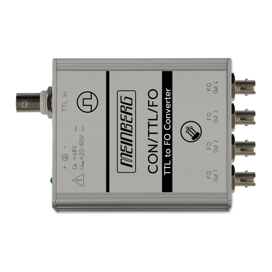
Page 17: Con/Ttl/Fo
(TTL, RS422 or FO) into one or more FO (fiber optical) output signals. 1.) CON/TTL/FO: TTL input via BNC connector to one FO output 2.) CON/TTL/FO-x: TTL input (BNC) to x (2, 3 or 4) FO outputs 3.) CON/422/FO: RS422 input via 9pin-DSub connec- tor to one FO output 4.) CON/422/FO-x: RS422 input (DSub) to x (2, 3 or... -
Page 18: Con/Fo/Ttl
RS422 output signal via female 9pin-DSub connector (Pin7: +OUT, Pin8: -OUT) Signal delay: Delay of the electrical slope, detected with CON/TTL/FO and CON/FO/TTL: rising edge: 45ns falling edge: 45ns (plus the delay caused by the optical fiber: approx. 4,9 ns/m) Data Rate: max. -
Page 19: Con/232/Fo
3.4 CON/232/FO The fiber optic module CON/232/FO converts a RS- Standard variants (for RxD and TxD) 232 signal (TxD and RxD) into optical signals. CON/232/FO: RS-232 (DB9 male) to 1 x FO In and 1 x FO Out Variants (TxD only), also as diplexer CON/232/FO-1: TxD In (DB9 male) to 1 x FO Out Optional up to 4 x FO Out: CON/.../FO-x /Output CON/232/FO (RxD) -
Page 20: Con/Tcm/Fo Und Con/Fo/Tcm
3 Fiber Optic Converter Overview 3.5 CON/TCM/FO und CON/FO/TCM These fiber optic modules carry an amplitude mod- Variant to convert a Time Code AM signal to FO ulated Time Code AM signal over an optical fiber. CON/TCM/FO: Time Code In (BNC) to 2 x FO Out Signal delay: 60 s Variant to back-convert the FO signal to Time Code CON/FO/TCM: FO In to 2 x Time Code Out (BNC) -
Page 21: Con/Ttl/Fos
3.6 CON/TTL/FOS The fiber optic module CON/TTL/FOS converts an in- Standard variants put signal (TTL, RS-422 or FO) into one or more FO PPS, PPM, IRIG-B DCLS, 10MHz (fiber optical) output signals for single mode. CON/TTL/FOS: TTL In (BNC) to 1 x FO Out CON/422/FOS: RS-422 In (DB9 male) to 1 x FO Ou CON/FOS/FOS: FO In to 1 x FO Out Option: up to 4 x FO Out... -
Page 22: Con/Fos/Ttl
3 Fiber Optic Converter Overview 3.7 CON/FOS/TTL The fiber optic module CON/FOS/TTL converts a sin- Standard Varianten gle mode FO input signal into one or more electrical PPS, PPM, IRIG-B DCLS, 10 MHz output signals (TTL or RS-422). CON/FOS/TTL: FO In to 2 x TTL Out (BNC) CON/FOS/422: FO In to 1 x RS-422 Out (DB9 fe- male) CON/FOS/TTL/422: FO In to 1 x RS-422 and 1 x TTL...
Need help?
Do you have a question about the CON/TTL/FO and is the answer not in the manual?
Questions and answers