Table of Contents
Advertisement
Advertisement
Table of Contents

Related Manuals for DirectOut Technologies ANDIAMO 2.XT


Summary of Contents for DirectOut Technologies ANDIAMO 2.XT
- Page 1 ANDIAMO 2.XT (SRC) Hardware Guide Version 2.1...
- Page 2 DirectOut GmbH cannot be held responsible for any misleading or incorrect information provided throughout this manual. DirectOut GmbH reserves the right to change specifications at any time without notice. DirectOut Technologies® is a registered trademark of the DirectOut GmbH. © DirectOut GmbH, 2016 page 2 of 56...
-
Page 3: Table Of Contents
Connecting Word clock ................38 Connecting USB ..................38 Connecting AES3 ..................39 Connecting Analog ..................40 CHAPTER 5: Menu Navigation Signal Routing ..................... 42 System Settings ..................43 ANDIAMO 2.XT (SRC) Hardware Guide - Version 2.1 page 3 of 56... - Page 4 CHAPTER 6: Troubleshooting and Maintenance Troubleshooting ................... 45 Maintenance ....................45 CHAPTER 7: Technical Data Appendix A - DSUB-25 Pin assignment Index page 4 of 56 ANDIAMO 2.XT (SRC) Hardware Guide - Version 2.1...
-
Page 5: About This Document
This document relates to: • ANDIAMO 2.XT - firmware version 6.1 • ANDIAMO 2.XT SRC - firmware version 6.1 The front panel of the two versions differs and the related sections are marked accordingly. ANDIAMO 2.XT (SRC) Hardware Guide - Version 2.1... -
Page 6: Chapter 1: Overview Introduction
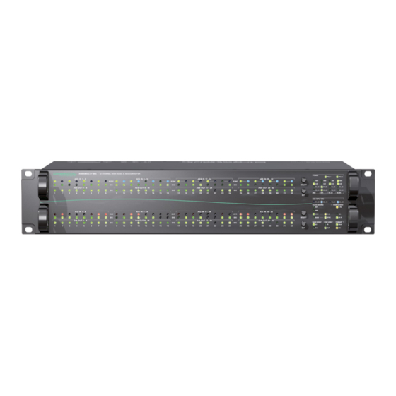
CHAPTER 1: Overview CHAPTER 1: Overview Introduction The ANDIAMO 2.XT is a high quality AD/DA converter for MADI and AES signals. It provides two MADI inputs and outputs, 16 AES3 inputs and outputs and 32 channels analog inputs and outputs. -
Page 7: Feature Summary
(84 V to 264 V AC / 47 Hz to 63 Hz / safety class 1) Applications ANDIAMO 2.XT (SRC) can be used for conversion, monitoring, recording and routing of analog and digital signals. Typical applications include: • monitoring digital audio •... -
Page 8: Chapter 2: Legal Issues & Facts
We would like to remind you to please check carefully whether the failure is caused by erroneous configuration, operation or connection before sending parts for repair. page 8 of 56 ANDIAMO 2.XT (SRC) Hardware Guide - Version 2.1... -
Page 9: First Aid (In Case Of Electric Shock)
Check their pulse and reanimate if their respiration is poor. Lay the body down and turn it to one side. Call for a doctor immediately. • Having sustained an electric shock, always consult a doctor. ANDIAMO 2.XT (SRC) Hardware Guide - Version 2.1 page 9 of 56... -
Page 10: Updates
This guide refers to firmware version 6.1 Intended Operation ANDIAMO 2.XT (SRC) is designed for conversion of audio signals from digital to digital, analog to digital and vice versa. In this context digital audio refers to a MADI signal (AES10) and AES signal (AES3). -
Page 11: Conformity & Certificates
Only stamped parcels will be accepted! WEEE-Reg.-No. DE 64879540 Contact DirectOut GmbH Leipziger Str. 32, 09648 Mittweida, Germany Phone: +49 (0)3727 5665-100 Fax: +49 (0)3727 5665-101 Mail: sales@directout.eu www.directout.eu ANDIAMO 2.XT (SRC) Hardware Guide - Version 2.1 page 11 of 56... -
Page 12: Contents
CHAPTER 2: Legal issues & facts Contents The contents of your ANDIAMO 2.XT package should include: • 1 x ANDIAMO 2.XT (SRC) (19’’, 2 RU) • 2 x power chord • 2 x fixing unit for power plug • 1 x Hardware Guide To complete the delivery please download from the product page on the DirectOut website (www.directout.eu):... -
Page 13: Accessories
BREAKOUT.AN8 - analog input / output, 8 channels Article code: DOBOB0719 BREAKOUT.AN16I - analog input, 16 channels Article code: DOBOB0720 BREAKOUT.AN16O - analog output, 16 channels Article code: DOBOB0721 ANDIAMO 2.XT (SRC) Hardware Guide - Version 2.1 page 13 of 56... - Page 14 BREAKOUT.AES or AESid transferring 8 audio channels, length 0.5 m DSUB25.AES100 Digital patch cable for connection with DOCAA0333 BREAKOUT.AES or AESid transferring 8 audio channels, length 0.5 m page 14 of 56 ANDIAMO 2.XT (SRC) Hardware Guide - Version 2.1...
-
Page 15: Chapter 3: Installation
SC / SC Version N OT E ! Retain the protective cap if the optical port is unused. This will protect against soiling which can lead to malfunction. ANDIAMO 2.XT (SRC) Hardware Guide - Version 2.1 page 15 of 56... - Page 16 This device may operate with only one power supply. To provide power supply redundancy, it is recommended to connect both PSU 1 and PSU 2 to independent power supplies with separate fuses. page 16 of 56 ANDIAMO 2.XT (SRC) Hardware Guide - Version 2.1...
- Page 17 N OTE To update the fi rmware an installed USB Serial driver (Windows) and the Update Tool are necessary. The software and the installation instructions are available at www.directout.eu. ANDIAMO 2.XT (SRC) Hardware Guide - Version 2.1 page 17 of 56...
- Page 18 Installation of ‘ANDIAMO Remote’ (Windows® / OS X®) • download the ‘Software Guide ANDIAMO Remote‘ • download the ‘ANDIAMO Remote’ application • follow the installation instructions in the ‘Software Guide ANDIAMO Remote’ page 18 of 56 ANDIAMO 2.XT (SRC) Hardware Guide - Version 2.1...
- Page 19 CHAPTER 3: Installation This page is left blank intentionally. ANDIAMO 2.XT (SRC) Hardware Guide - Version 2.1 page 19 of 56...
-
Page 20: Chapter 4: Operation Introduction
• 44.1 kHz or 48 kHz = 1 FS • 88.2 kHz or 96 kHz = 2 FS • 176.4 kHz or 192 kHz = 4 FS page 20 of 56 ANDIAMO 2.XT (SRC) Hardware Guide - Version 2.1... -
Page 21: Global Control
Note that an unlit LED does not guarantee that the device is free of voltage. To ensure that the device is completely disconnected from mains voltage, the power chords must be disconnected. ANDIAMO 2.XT (SRC) Hardware Guide - Version 2.1 page 21 of 56... -
Page 22: Menu Control
Blinking LEDs are also used to indicate an error (e.g. missing sync). Concentrate on the section where one LED is blinking and the remaining LEDs are glowing weak. page 22 of 56 ANDIAMO 2.XT (SRC) Hardware Guide - Version 2.1... - Page 23 • AD/DA calibration in 0.1 dB increments • Configuration of the system fan control • Redundancy Modes • USB Embedder • Preset management • Display Dark The settings are stored inside the device. ANDIAMO 2.XT (SRC) Hardware Guide - Version 2.1 page 23 of 56...
-
Page 24: Clocking
LED (green): indicates the lock/sync status of SYNC** selected MADI input LED ON = MADI input signal is in sync LED blinking = MADI input signal of is locked but not in sync page 24 of 56 ANDIAMO 2.XT (SRC) Hardware Guide - Version 2.1... - Page 25 (port 1, port 2,...): lowest input port receiving a valid AES signal and SRC switched off A SYNC LED indicates the sync state for each port individually. ANDIAMO 2.XT (SRC) Hardware Guide - Version 2.1 page 25 of 56...
- Page 26 17 ..24 / 25..32) LED ON = Sample rate converter group active LED OFF = Sample rate converter group not active NOT E Latency introduced by SRC: less than 140 samples page 26 of 56 ANDIAMO 2.XT (SRC) Hardware Guide - Version 2.1...
- Page 27 CHAPTER 4: Operation This page is left blank intentionally. ANDIAMO 2.XT (SRC) Hardware Guide - Version 2.1 page 27 of 56...
- Page 28 The redundancy mode is adjusted via remote control. Default setting ‘Standard’: The MADI input that locks fi rst will be selected automatically, switchover at signal loss, no revert when signal is regained. page 28 of 56 ANDIAMO 2.XT (SRC) Hardware Guide - Version 2.1...
-
Page 29: Sample Rates
96k Frame signal has been detected. With 48k Frame signals no distinction is possible between 1 FS or 2 FS or 4 FS - so the scaling factor has to be set manually. ANDIAMO 2.XT (SRC) Hardware Guide - Version 2.1 page 29 of 56... -
Page 30: Output Format
T I P To convert a 2 FS MADI signal from 48k Frame (SMUX) into a 96k Frame signal, set the converter to 2 FS operation and activate 96k Frame. page 30 of 56 ANDIAMO 2.XT (SRC) Hardware Guide - Version 2.1... -
Page 31: Level Settings
The version is marked on the rear panel (I/O level). TI P Additional settings via remote control: • Output gain/level trim for individual channels • AD/DA calibration in 0.1 dB increments ANDIAMO 2.XT (SRC) Hardware Guide - Version 2.1 page 31 of 56... -
Page 32: Level Meters - Analog I/O
LED (green): indicates signal level of channel output LED ON = analog output signal equals to more than -80 dBFS The light intensity of the LEDs depends on the audio level. page 32 of 56 ANDIAMO 2.XT (SRC) Hardware Guide - Version 2.1... -
Page 33: Level Meters - Digital I/O
LED (blue): indicates activation status of sample rate AES IN SYNC converter at the AES input (Port 1 - 16) LED ON = SRC active LED OFF = SRC not active ANDIAMO 2.XT (SRC) Hardware Guide - Version 2.1 page 33 of 56... -
Page 34: Signal Routing
(01 to 16 @ 2 FS, 01 to 08 @ 4 FS) MADI input channel 33 to 64 (17 to 32 @ 2 FS, 09 to 16 @ 4 FS) page 34 of 56 ANDIAMO 2.XT (SRC) Hardware Guide - Version 2.1... - Page 35 Matrix Mode active Extended Routing not active Both MADI outputs work in parallel. Two LED columns blinking alternately. Matrix Mode active Extended Routing active MADI outputs may transmit individual signals. ANDIAMO 2.XT (SRC) Hardware Guide - Version 2.1 page 35 of 56...
- Page 36 ID 01 + 4 samples ID 02 + 4 samples NOT E To ensure proper detection of delay compensation no other device must be connected in between two ANDIAMOs. page 36 of 56 ANDIAMO 2.XT (SRC) Hardware Guide - Version 2.1...
-
Page 37: Connecting Madi
The MADI outputs may work in parallel or idependent from each other - see “Extended Routing” on page 35. TI P Additional settings via remote control: • Routing Matrix (Matrix Mode / Extended Routing) • Redundancy Modes ANDIAMO 2.XT (SRC) Hardware Guide - Version 2.1 page 37 of 56... -
Page 38: Connecting Word Clock
Connect for fi rmware updates and remote control here. The use of the USB port requires the USB Serial driver installed. The driver and the installation instructions are available at the ANDIAMO 2.XT product page at www.directout.eu. page 38 of 56... -
Page 39: Connecting Aes3
N OT E The pinout of the digital and analog I/O is different. Check for appropriate cabling to ensure proper operation and to avoid damages caused by improper connections. ANDIAMO 2.XT (SRC) Hardware Guide - Version 2.1 page 39 of 56... -
Page 40: Connecting Analog
Analog audio input (balanced) - connect audio channels 25 to 32 here The pinout complies with AES59 (‘TASCAM pinout’) see „Appendix A - DSUB-25 Pin assignment“ on page 48. page 40 of 56 ANDIAMO 2.XT (SRC) Hardware Guide - Version 2.1... - Page 41 The line output is not servo balanced. Do not connect the negative lead to ground. This may cause damage at the output stage. Observe the technical specifications listed in this document. ANDIAMO 2.XT (SRC) Hardware Guide - Version 2.1 page 41 of 56...
-
Page 42: Chapter 5: Menu Navigation
SELECT (SRC Version only) SELECT SELECT SELECT SELECT Output sources Analog MADI 01..32 MADI 33..64 Fallback Mode* Mute * Fallback mode availabe for MADI output only - see page 36. page 42 of 56 ANDIAMO 2.XT (SRC) Hardware Guide - Version 2.1... -
Page 43: System Settings
Blinking LEDs are also used to indicate an error (e.g. missing sync). Concentrate on the section where one LED is blinking and the remaining LEDs are glowing weak. ANDIAMO 2.XT (SRC) Hardware Guide - Version 2.1 page 43 of 56... - Page 44 CHAPTER 5: Menu Navigation This page is left blank intentionally. page 44 of 56 ANDIAMO 2.XT (SRC) Hardware Guide - Version 2.1...
- Page 45 To clean the device, use a soft, dry cloth. To protect the surface, avoid using cleaning agents. N OT E ! The device should be disconnected from the power supply during the cleaning process. ANDIAMO 2.XT (SRC) Hardware Guide - Version 2.1 page 45 of 56...
- Page 46 • 4 x DSUB-25 (8 analog audio channels each - balanced), AES59 compliant Analog Output • 4 x DSUB-25 (8 analog audio channels each - balanced), AES59 compliant • The outputs are not servo balanced. page 46 of 56 ANDIAMO 2.XT (SRC) Hardware Guide - Version 2.1...
- Page 47 • 1 x BNC socket (75 Ω impedance) - input • 1 x BNC socket (75 Ω impedance) - output • Termination 75 Ω switchable • AES11 (DARS supported) • 1 x USB 2.0 socket (Type B) ANDIAMO 2.XT (SRC) Hardware Guide - Version 2.1 page 47 of 56...
- Page 48 CH 4 − CH 4 IN − CH 3 + CH 3 IN + CH 2 − CH 2 IN − CH 1 + CH 1 IN + page 48 of 56 ANDIAMO 2.XT (SRC) Hardware Guide - Version 2.1...
- Page 49 Appendix A - DSUB-25 Pin assignment This page is left blank intentionally. ANDIAMO 2.XT (SRC) Hardware Guide - Version 2.1 page 49 of 56...
- Page 50 Fuses ............46 System Settings ........43 Impedance (input/output) ......47 Technical Data .......... 46 Intended Operation ........10 THD (AD & DA) ........47 Troubleshooting ........45 page 50 of 56 ANDIAMO 2.XT (SRC) Hardware Guide - Version 2.1...
- Page 51 Index Updates ........... 10 USB ............7 Warranty ..........10 ANDIAMO 2.XT (SRC) Hardware Guide - Version 2.1 page 51 of 56...
- Page 52 Notes page 52 of 56 ANDIAMO 2.XT (SRC) Hardware Guide - Version 2.1...
- Page 53 Notes ANDIAMO 2.XT (SRC) Hardware Guide - Version 2.1 page 53 of 56...
- Page 54 Notes page 54 of 56 ANDIAMO 2.XT (SRC) Hardware Guide - Version 2.1...
- Page 55 Notes ANDIAMO 2.XT (SRC) Hardware Guide - Version 2.1 page 55 of 56...
- Page 56 DirectOut GmbH Leipziger Strasse 32 T: +49-3727-5665-100 09648 Mittweida F: +49-3727-5665-101 Germany www.directout.eu...
Need help?
Do you have a question about the ANDIAMO 2.XT and is the answer not in the manual?
Questions and answers