Table of Contents
Advertisement
Quick Links
CONTENTS
Introduction
Physical Installation
Mounting to the wall
Pipe hole configuration
Terminal designations
Relays
INTRODUCTION
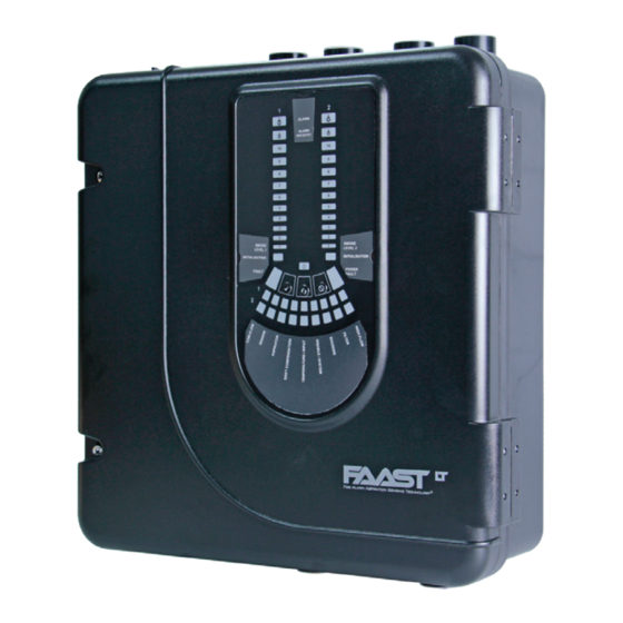
The LT-200 FL20 Series is part of the Fire Alarm Aspiration Sensing
Technology
(FAAST) family. FAAST is an advanced fire detection
®
system for use where early warning and very early warning are a
requirement. The system continuously draws air from the controlled
environment through a series of sampling holes to monitor the
environment for smoke particulate.
The FL20 is the addressable version of the FAAST LT-200 range,
communicating with the CIE (Fire Panel) via a proprietary loop protocol.
It is available in 3 different models:
FL2011EI-HS - Has single channel capability with one high sensitivity
FL2012EI-HS - Has single channel capability with two high sensitivity
smoke sensors in a common chamber for coincidence detection.
FL2022EI-HS - Has two channel capability with two high sensitivity
smoke sensors in separate chambers. (One sensor for each channel).
This guide provides information for mounting the unit, basic installation
and advice on pipe layout designs, together with an overview of using
the PipeIQ software to achieve EN54 compliant designs. For more
complex designs using increased functionality (experienced users
only) please see the FAAST LT-200 Advanced Setup and Control
Guide - reference D200-100-01.
Important Note
Aspirating Smoke Detectors supplied and installed within the EU must
conform to the EU Construction Products Regulation (CPR) 305/2011
and the related European Product Standard EN 54-20. FAAST LT-200
has been tested and certified to ensure that it conforms to the necessary
Standards, but strict adherence to this instruction guide is advised to
ensure that the installation meets the requirements of the CPR.
The PipeIQ software is a design application to help a user create or
verify EN54 compliant pipe layouts, and to allow configuration of the
FAAST LT-200 unit. (Note: Always check you are using the latest
version. It can be downloaded from www.systemsensoreurope.com.)
The performance of this system is dependent upon the pipe
network. Any extension or modification to the designed installation
may cause improper operation. The operational effects of such
changes need to be verified using the PipeIQ design software.
This equipment and all associated pipe work must be installed in
accordance with all relevant codes and regulations.
D200-102-01
Fire Alarm Aspiration Sensing Technology
FL2011EI-HS FL2012EI-HS FL2022EI-HS
ADDRESSABLE FAAST LT-200 MODELS
1
Front Panel
1
Buttons
1
Testing
2
Service
2
PipeIQ™ Software
2
3
Appendix A -
4
4
Appendix B -
5
Practical Pipe Designs
5
6
6
6
QUICK INSTALLATION GUIDE
6
7
8
8
9
10
11
PARTS LIST
Description
SPECIFICATIONS
Electrical Characteristics
Voltage Range:
Supply Current: 1 Channel: 170mA (typical); 360mA (max) @ 24
Com. Loop Supply Voltage: 15 - 29 VDC (Loop current ≤ 900mA)
Com. Loop Standby Current: @ 24V: 900 µA max. (2 sensors + 2
Module Isolator Characteristics
Maximum rated switching current
(under short circuit, Is max): 0.9A @ ≤ 29V
Maximum leakage current (IL max)
with the switch open (isolated state): 15mA
Maximum series impedance with
the switch closed (Zc max): 190 m ohm at 15Vdc; 1A
Power Reset:
Configurable Input:
Relay Contact Ratings:
Environmental Ratings
Temperature:
Relative Humidity:
Flow Fault:
IP Rating:
Mechanical
Wiring:
1
®
Quantity
1
1
6
1
3
2
1
1
1
1
19 - 31.5 VDC
VDC 25
C (excluding sounders)
o
2 Channel: 270mA (typical); 570mA (max) @ 24
VDC 25
C (excluding sounders)
o
channels polled once every 5s)
0.5s
Activation Time: 2s (min)
2.0 A @ 30 VDC, 0.5A @ 30 VAC
-10°C to 55°C
10% to 93% (non-condensing)
± 20% of the reference flow
65
0.5 mm² to 2 mm² max
ENGLISH
I 56- 6575- 005
I56-6575-005
Advertisement
Table of Contents

Subscribe to Our Youtube Channel
Related Manuals for System Sensor FL2011EI-HS


Summary of Contents for System Sensor FL2011EI-HS
-
Page 1: Table Of Contents
CIE (Fire Panel) via a proprietary loop protocol. Front Panel Labelling Pack It is available in 3 different models: Wiring Diagram Label FL2011EI-HS - Has single channel capability with one high sensitivity Quick Installation Guide smoke sensor. SPECIFICATIONS FL2012EI-HS - Has single channel capability with two high sensitivity smoke sensors in a common chamber for coincidence detection. -
Page 2: Front Panel Labels
Maximum Single Pipe Length: 100m (Class C) Maximum Branched Pipe Length: 200m (2 x 100m, Class C) Maximum Number of Holes: See Table 1A Pipe Spec (EN54-20 Compliance): to EN 61386 Figure 3: (Crush 1, Impact 1, Temp 31) Remove Backing to Outside Pipe Diameter: 25mm (nom) or 27mm (nom) Stick Cover Down... -
Page 3: 2-Pin Terminal Block
Pipe Hole Configuration Figure 7: Sequence (1 to 9) to Mount the Detector on the Bracket Figure 8 below shows the pipe holes available on the unit. Each unit has 2 pipe holes per channel connected together like a T-Piece. If 99 mm using a 1 channel unit, holes 3 and 4 do not function. -
Page 4: Exhaust Pipe
Exhaust Pipe Whenever the FAAST LT-200 is installed outside the risk area, return of the exhaust air back into the protected area can reduce flow faults due to pressure difference. SAMPLING AREA IMPORTANT NOTES 1) Do not glue the pipes into the inlets or outlets of the FAAST LT- 200 unit. - Page 5 Fitting the Terminal Blocks WARNING: Switching Inductive Loads To insert the terminal blocks into the unit use the following method: FAAST LT Insert a corner of the block into the slot (see a). Push the length of the block into the slot until the block ‘clicks’ into place, the 2 upper hooks on the block should be visible (see c).
-
Page 6: Setting The Addresses
Use a screwdriver to rotate the wheels to the desired address. The selected address refers to channel 11a: FL2011EI-HS / FL2012EI-HS 1 Channel Detector 1; on 2 channel units the device assigns the next (+1) module address to channel 2 automatically. -
Page 7: Indicators And Fault Descriptions
Table 4: Front Panel Indicators and Fault Descriptions INDICATOR ACTION WARNING OR TROUBLE COMMENT / ACTION CHANNEL 1/2 ALARM ON Red Channel is in alarm (relay is set ON with Default setting (Set by panel) no delay) 1 BLINK Green When sensor is polled Not when in alarm (Polled by panel) -
Page 8: Smoke Sensor
A A L L A A R R M M P P R R E E A A L L A A R R M M A A L L A A R R M M P P R R E E A A L L A A R R M M S S M M O O K K E E Password Sequence to Enter Maintenance Mode smoke sensors continue to communicate with the panel). - Page 9 Note 2: To connect a FAAST LT-200 to a PC using the USB port, the Honeywell Products and Solutions Sàrl PipeIQ software must be running on the PC and the device must be in (Trading as System Sensor Europe) Maintenance mode (See Password Sequence to Enter Maintenance Zone d’activités La Pièce 16 Mode section previously).
-
Page 10: Pipeiq™ Pipe System Design
APPENDIX A - PipeIQ™ and PIPE SYSTEM DESIGN USING PipeIQ™ for SYSTEM DESIGN Pipe Design Methodology Flow Chart PIPE DESIGN METHODOLOGY FLOW CHART PipeIQ is a design application to help a user create EN54 compliant Start Project pipe layouts. Generating a suitable working design will require some and create thought and understanding of the interacting variables in an aspirating pipe layout... - Page 11 APPENDIX B - PRACTICAL PIPE DESIGNS for ASPIRATING SYSTEMS The following tables show some typical EN54 CLASS C PIPE DESIGNS WITH SINGLE SAMPLE HOLE/END HOLE SIZE AND 10m SPACING compliant pipe designs for FAAST LT-200 1 PIPE devices with different overall pipe lengths. Pipe Number Hole End Air Flow Average Alarm Fan Total hole Each design has a one size sample hole for Length ...
- Page 12 CLASS C PIPE DESIGNS WITH SINGLE SAMPLE HOLE SIZE (Inc. SAMPLING END HOLE) AND 10m SPACING ‐ 2 PIPE (T‐FORM) Pipe Number Hole Air Flow Average Alarm Fan Total Length of holes size flow balance sensitivity level hole area (m) (mm) (I/min) (%/m) ) 80 X ‐ ‐ ‐ ‐ ‐ ‐ ‐ 70 X ‐ ‐ ...
- Page 13 CLASS A PIPE DESIGNS WITH SINGLE SAMPLE HOLE SIZE (Inc. SAMPLING END HOLE) AND 10m SPACING 1 PIPE Pipe Number Hole End Air Flow Average Alarm Fan Total hole Length of holes size hole flow balance sensitivity level area (m) (mm) (mm) (I/min) (%/m) ) 80 X ‐ ‐ ‐ ‐ ‐ ‐ ‐ ‐ ...
Need help?
Do you have a question about the FL2011EI-HS and is the answer not in the manual?
Questions and answers