
Subscribe to Our Youtube Channel
Related Manuals for Stepp OJK-H series

Summary of Contents for Stepp OJK-H series
- Page 1 Rev. 12/2014 OPERATIONS/MAINTENANCE/PARTS MANUAL Diesel Burner Systems 12325 River Road North Branch MN 55056 ~ Phone: 651-674-4491 ~ Fax: 651-674-4221 www.steppmfg.com...
- Page 2 (1) year from the date of purchase. Stepp Mfg., at its discretion, will provide for the repair or replacement of any part found upon examination by Stepp Mfg. to be defective, except as noted below. Such repair or re- placement will be free of charge to the original purchaser for a period of one (1) year from the date of purchase, except as noted below.
- Page 3 OJK Stepp Oil Jacketed Kettle Thank you for selecting Stepp highway maintenance equipment. We are confi- dent you will be satisfied with the Stepp Oil Jacketed Kettle. Stepp Manufactur- ing is backed by over 70 years of experience in the design and manufacture of highway maintenance equipment.
-
Page 4: Table Of Contents
This manual explains the basic operations, maintenance and use of the Stepp OJK Oil Jacketed Kettle. The main objective of this equipment is to melt rubberized crack seal-... - Page 5 Before Starting or Operating this Machine Understand and observe all the following Warnings, Cautions, and Notes. WARNINGS This equipment contains mechanical and heating components that may cause serious injury or death if not handled or maintained properly. All personnel must be properly trained in the operation and maintenance of this equipment.
-
Page 6: Quick Specs
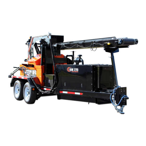
The Stepp Oil Jacketed Kettle is the perfect blend of PERFORMANCE, DURABILITY, and VERSATILITY for your pothole patching needs and budget! Quick Spec OJK 185 OJK 275 OJK 400 Capacity 190 Gallon 280 Gallon 440 Gallon Heat Transfer 110 Gallon... -
Page 8: Description
DESCRIPTION The Stepp OJK is designed to melt and apply rubberized crack sealing compounds to fill cracks in the roadway surface. The OJK uses a tank surrounded by an oil jacket filled with heat transfer oil. The heat transfer oil is heated by a diesel fired burner and is circulated in the oil jacket by a pump. In addition to the oil jacket there is a coil surrounding the agitating auger in the tank. - Page 9 DESCRIPTION Component Location 1. Wand Pressure Control (WPC) Valve — Controls the amount of pressure being applied to the hose & wand when the pump saver system is not being used. Also allows the operator to divert the flow of material back to tank for circulation, or to the wand for application to the road surface.
- Page 10 DESCRIPTION Component Location 1. 24V Alternator — Provides electrical power to the wand and hose heating elements. 2. Engine Control Panel — Provides a means of controlling engine functions. 3. Engine Fuel Filter — Provides clean fuel to engine. (not shown) 4.
- Page 11 DESCRIPTION Component Location 1. Wand Pressure Control (WPC) Valve — Controls the amount of pressure being applied to the hose & wand when the pump saver system is not being used. Also allows the operator to divert the flow of material back to tank for circulation, or to the wand for application to the road surface.
- Page 12 275°F. Product Pump: The Stepp OJK is equipped with a hydraulically operated product pump with "Pump & Re- verse" control. In the "Pump" position, the pump delivers product from the tank, through the hose, and to the wand for application to the road surface. In the "Reverse" position the pump draws the product out of the product pump, plumbing, and WPC (wand pressure control) valve to prevent freeze-up when the unit is shutdown.
- Page 13 Controls Stepp AKC Advanced Kettle Controls: The Stepp OJK shall be equipped with the Stepp AKC Advanced Kettle Control, can buss PLC control system. The AKC controller shall monitor and control all burner functions, pump- ing and agitation controls, kettle interlock safety systems, autoloader controls and operations, auger safety shutdown, and diagnostics for the burner control system.
- Page 14 DESCRIPTION Wand Pressure Control Valve CAUTION: Operators must understand the proper operation of the WPC valve located on the top rear of the unit. The purpose of this valve is to direct the flow of product either back to the tank (during start- up to assist melting) or to the wand (during crack filling operations).
- Page 15 DESCRIPTION Misc. Heated Hose & Wand: The application wand and hose are equipped with an internal heating element. The element is powered by the 24 volt alternator run by the engine. This heating element prevents the prod- uct from "freezing" in the hose and wand. The electric wand heat control should be turned on 20 to 30 minutes before trying to pump material through the hose and wand.
-
Page 18: Operations
OPERATIONS Basic Operations Pre-start Checks: The burner system is equipped with a safety interlock system that prevents the burner from igniting unless the engine is running. WARNING: This safety interlock must be tested each time before the engine is started. Fol- low the steps below prior to engine start. - Page 19 OPERATIONS Basic Operations Transporting: 1. Shut off the burner and the engine. 2. Securely latch the loading chute and recirculating flange. 3. Secure the wand and hose assembly in the hanger. 4. Attach the unit to the towing vehicle being certain hitch is fully engaged, connect safety chains, electrical connector, and breakaway switch (if equipped), retract the landing gear and secure in the up position.
- Page 20 OPERATIONS Engine Engine Starting: NOTE: Be sure all pre-start checks are complete prior to starting engine. 1. Fill fuel tank. 2. Turn key switch to the ON (right) position. 3. Hold yellow glow plug button down for 30-60 seconds. 4. Press and hold the unloader button (this allows the engine to start with out hydraulic load on the engine).
- Page 21 OPERATIONS Burner and Pump Burner & Pump Operations: 1. Turn the main power switch to the ON position. 2. Turn the burner switch ON and the burn- er will ignite. 3. Set product thermostat to the product manufacturers recommended temperature. Thermostat will display the set point and the actual temperature of the product.
- Page 22 OPERATIONS Application Standard Application Operations: NOTE: For units equipped with pump saver option installed, the pump will only function when the trigger is pulled on the wand. Application Operations with "Pump Saver”: 1. Position the WPC valve fully to the "Wand" position. 2.
- Page 23 8. Turn key to OFF position to shutdown the engine. CAUTION: The Stepp OJK requires special shutdown procedures that must be followed to maximize safety and equipment performance. These procedures will assure that the hose and wand always have product in them to avoid an overheated element. (DO NOT suck the product back out of the wand and hose assembly).
- Page 24 OPERATIONS Helpful Hints 1. It is recommended that the product level be drawn down to ¼ capacity or less prior to shutdown if the machine is not going to be used for two days or more. This will decrease the startup time next time the machine is used. However, if the equipment will be used the next day leave the unit ½...
- Page 25 OPERATIONS Optional Equipment Optional Air Compressor: 100 CFM rotary screw compressor, direct coupled to the Kubota engine. 1. Start the engine (refer to engine start). 2. Set throttle to adjust the desired air flow using the supplied pressure gauge. 3. Connect the air hose to the quick connector and open the supply valve. Optional Autoloader: The optional autoloader will automatically add blocks of sealant to the kettle as you apply ma- terial from the wand.
- Page 28 OJK MAINTENANCE SCHEDULE ITEM OPERATION TO PERFORM HOURS DAILY EVERY EVERY EVERY NEEDED 12 MO 24MO ENGINE Refer to the engine manufacturers manual insert. Check engine oil level, add oil as need- Change engine oil and filter. COOLANT Check coolant level. COOLANT Flush cooling system and replace cool- ant.
- Page 29 OJK MAINTENANCE SCHEDULE ITEM OPERATION TO PERFORM HOURS DAILY EVERY EVERY EVERY NEEDED 12 MO 24MO BURNER ELECTRODES Check electrodes for wear and proper adjustment. NOZZLE Replace fuel nozzle with same size and style. FILTER Replace burner fuel filter. F-HEAD Check condition of F-head on burner.
- Page 30 OJK MAINTENANCE SCHEDULE ITEM OPERATION TO PERFORM HOURS DAILY EVERY EVERY EVERY NEEDED 12 MO 24MO HEATED HOSE JACKET Check condition of hose safety jacket. Replace if damaged. HOSE Check condition of hose. Replace if damaged. HOSE Replace hose. CONNECTION Check condition of tightness of hose and wire connections.
- Page 31 OJK MAINTENANCE SCHEDULE ITEM OPERATION TO PERFORM HOURS DAILY EVERY EVERY EVERY NEEDED 12 MO 24MO CHASIS TIRES Check tire condition and pressure. BRAKES Check brake operation. BRAKES Inspect and adjust brake shoes, drums, and components. LUG NUTS Check lug nuts for proper torque. BEARINGS Inspect wheel bearings and repack with grease.
- Page 32 OJK MAINTENANCE RECORD DATE MAINTENANCE PERFORMED HOUR METER SERVICED BY All maintenance items must be performed according to the maintenance schedules and documented for warranty coverage to be effective.
- Page 33 OJK MAINTENANCE RECORD DATE MAINTENANCE PERFORMED HOUR METER SERVICED BY All maintenance items must be performed according to the maintenance schedules and documented for warranty coverage to be effective.
- Page 34 OJK MAINTENANCE RECORD DATE MAINTENANCE PERFORMED HOUR METER SERVICED BY All maintenance items must be performed according to the maintenance schedules and documented for warranty coverage to be effective.
-
Page 35: Maintenance
MAINTENANCE Engine Oil & Filter Change: 1. Run engine until operating temperature is reached, then shut OFF engine. 2. Place drain pan under oil drain hose. 3. Open oil drain valve and drain oil from the engine. 4. Close the oil drain valve. 5. - Page 36 MAINTENANCE Hydraulic System Filter Change: 1. Position drain pan under filter. 2. Remove oil filter. 3. Lubricate gasket of new filter with hydraulic oil. 4. Install new filter, hand tighten. 5. Start unit and check for leaks. 6. Shutdown unit then check hydraulic oil level. Hydraulic Oil Change: 1.
- Page 37 MAINTENANCE Heat Transfer Oil Level Check: 1. Remove oil fill cap on top of expansion tank. 2. Cold oil level should be at the lower notch and the hot level at the upper notch in the dip- stick. The cold level may also be checked by removing the cold oil level plug located to the lower left of the control panel on the rear of the machine.
- Page 38 MAINTENANCE Burner Fuel Filter Replacement: 1. Close fuel shutoff valve located at the fuel tank. 2. Remove the nut securing the canister to the fuel filter body. 3. Remove the canister and the filter element. 4. Replace the element with a new one. 5.
- Page 39 8. Lift heat transfer tubes and liner from combustion chamber housing. 9. Replace any insulation that is damaged or soaked with fuel or oil. Be sure to replace only with the same type insulation. Contact Stepp Mfg. for the proper insulation. 10. Install liner into heat transfer tubes.
- Page 40 MAINTENANCE Combustion Chamber Liner and Heat Transfer Tube Replacement (continued) 13. Slide the liner to the end of the housing where the burner is mounted, then install the re- taining clip over a tube and weld to the liner. NOTE: DO NOT weld on the heat transfer tubes.
- Page 41 MAINTENANCE Hot Asphalt Hose Replacement CAUTION: Do not remove hose without first removing the heating element or damage to heating element will result. Hose Removal: 1. Remove heating element from hose (refer to heating element removal procedures). 2. Disconnect all electrical connections from hose. 3.
- Page 42 MAINTENANCE Hose Heating Element Replacement (Functioning Element) Hose Heating Element Removal: These instructions assume the heating element is functioning properly. If the heating element does not function, refer to the instructions on the following pages. NOTE: If the hose is damaged, skip steps 1 through 3, activate wand heat for 15 minutes, then begin at step 4.
- Page 43 MAINTENANCE Hose Heating Element Replacement (Functioning Element) Hose Heating Element Installation: 1. Remove wand from hose at quick coupling. 2. Lay the hose out as straight as possible. 3. Install new compression fitting into cross fitting. NOTE: If hose DOES NOT contain material proceed with step 4. If hose CONTAINS material, replace step 4 with steps A &...
- Page 44 MAINTENANCE Hose Heating Element Replacement (Non-Functioning Element) Hose Heating Element Removal and Installation: These instructions assume the heating element is damaged and NOT functioning. If the heat- ing element functions properly, refer to the instructions on the previous page. The element may be damaged during removal, rendering it useless.
- Page 45 MAINTENANCE Wand & Boom Heating Element Replacement Wand & Boom Heating Element Removal and Installation: These instructions assume the heating element is damaged and not functioning. The element may be damaged during removal rendering it useless. A functioning heating element is slid into the wand or boom along side the non-functioning element.
-
Page 48: Troubleshooting
TROUBLESHOOTING Hydraulic System Items to Check /Service POSSIBLE CAUSE Plugged Strainer Screen Service strainer screen LACK OF PERFORMANCE Hydraulic Filter Plugged Replace hydraulic oil filter Collapsed Suction Hose Replace suction hose and ser- vice strainer screen Air Leak in Suction Hose Replace hose Low Fluid Level Fill reservoir to proper level... - Page 49 TROUBLESHOOTING Product Delivery Items to Check /Service POSSIBLE CAUSE PRODUCT PUMP Product in Tank not Melted Allow more time for product to melt DOES NOT TURN Safety Interlock Allow material to reach 275° on product and hose thermostat Pump Motor not Functioning Refer to “Hydraulic System”...
- Page 50 TROUBLE SHOOTING Product Pump Lack of flow from wand. Check for rotation No Rotation Engage pump control Refer to hydraulic Little or no of product pump. and observe engine system trouble change in RPM. Shooting. Rotation Definite RPM drop Check that the pump control is in Check that the product CAUTION:...
- Page 51 TROUBLE SHOOTING Electric Wand No heat, or low heat in wand or hose. With engine OFF, Check for loose pulleys and loose or missing belts on 24 volt alternator. Check for a dead battery, then check for an open resister or open wires Start engine, with wand 9 volts or less from battery to alternator, or a short-...
- Page 52 Test the Primary control- condition, turn main power ler function, replace if switch “off” then “on” again to Check the photo faulty. Contact Stepp reset the system. electric eye for a Mfg. if this does not cor- Check to see if : dirty lens and prop- rect problem.
- Page 53 TROUBLE SHOOTING Diesel Burner Component Primary Controller Burner MTD/Hard Wired NOTE: The primary controller can be bench tested for proper operation us- ing an automotive type, 12 volt battery as a power source. Refer to the wir- ing schematics for wire identification. 1.
- Page 54 TROUBLE SHOOTING Diesel Burner Photo Electric Eye NOTE: The Photo Electric Eye can be bench tested for proper oper- ation using an ohm meter. Assure the lens of the Photo Electric Eye is clean prior to testing. 1. Block off all light to the Photo Electric Eye. Test across the leads with your ohm meter;...
- Page 55 TROUBLE SHOOTING VIKING PUMP SYSTEM NPSHa not sufficient Air leaks into pump Pump has run dry Liquid temperature higher than expected Viscosity higher than expected Pump running too fast for application Abrasives present/parts not hardened Suction or differential pressure too high Suction valve not open Suction valve partially open Discharge valve not open...
- Page 56 NPSHa Not Sufficient - Pump cavitating due to inadequate suction side pressure. Buildup in suction lines, partially closed inlet valves, dirty strainers, or an increase in liquid viscosity are all potential causes. Air Leaks Into Pump - Pump pulling in air through a loose fitting or in a vortexing tank. Causes a cavitation-like noise. Pump Has Run Dry - Gear pumps that are frequently run dry will exhibit increased wear and seal problems.
- Page 58 REPLACEMENT PARTS DIESEL BURNER ITEM DESCRIPTION PART# Burner assembly w/ Primary Control (less fuel retention head and nozzle) ... A10008215 Burner assembly, complete w/ fuel retention head and nozzle ....... A10008105 Air Tube ......................509070 Photo electric eye (under ignition transformer) -With Connectors ..................
- Page 59 REPLACEMENT PARTS CONTROLS ITEM DESCRIPTION PART# Thermostat, Watlow 0-550°, EZ 12V EZ-ZONE– P10003540 Sensor, RTD Watlow 0-550° A10001017 Switch– SPST Toggle ON/OFF P10000180 Switch– ON/OFF/ON P10002877 Light– Call For Heat 12V P10000181 Hour Meter P10002722 20 Amp Breaker P10000179 ** Not Shown...
- Page 60 REPLACEMENT PARTS OVERHEAD BOOM Insert Heating Element Here To Hose ITEM DESCRIPTION PART # Boom 901280 Latch, boom transport and safety 901283 Support bearing 502006 Boom support (OJK 75 & 120) 901281 Boom swivel 520007 Union, 3/4" 513202 Nipple, 3/4" close 513211 Valve, 3-port WPC, 3/4"...
-
Page 61: Replacement Parts
REPLACEMENT PARTS 8’ / 12’ Heated Hose Insert heating For Units equipped with 8’/12’ Heated Hose w/Heated element here. Overhead Boom To wand 1 and 1c ITEM DESCRIPTION PART # 8' Hose Assembly with heating element ..............523089 12' Hose Assembly with heating element ............... 523093 Compression Fitting 3/8"... - Page 62 REPLACEMENT PARTS 15’ / 20’ HEATED HOSE ITEM DESCRIPTION PART # Compression Fitting assembly 523260 Bushing, reducing 513701 Plug 513208 Cross Fitting 513203 Nipple, close 513211 Valve, 3-port WPC 517022 Union 513202 Hose End 523084 Clamp assembly 523087 Hose only, specify 15 or 20 ft. 523083 Seal, quick coupling 509999...
- Page 63 REPLACEMENT PARTS TRIGGER WAND ITEM DESCRIPTION PART # Wand assembly , LONG Trigger Style 204056 Wand assembly, SHORT Trigger Style 204058 Handle, Adjustable Slide 520022 Switch, Trigger 526116 Wire Harness, Ultra-Lite Wand Call Heating Element, LONG Style 526113 Heating Element, SHORT Style 526118 Compression Fitting, LONG Style 1/2”...
- Page 64 REPLACEMENT PARTS HEATED WAND ITEM DESCRIPTION PART # Heating Element 526074 Compression Fitting 523260 Quick Coupling, male 510002 10 ft. Insulating Wrap, wand 520114 Mounting Bracket, switch (pump saver option only) Call Switch, pump saver (pump saver option only) 526057 Control Handle, for steel wand Call Control Handle with bushing, for aluminum wand...
- Page 65 REPLACEMENT PARTS NON-HEATED WAND ITEM DESCRIPTION PART # Wand assembly complete, steel (Includes items 1 - 4) 204004 Wand assembly complete, light weight aluminum (Includes items 1 - 4) 204026 Valve 517006 Coupling 513809 Spray Nozzle, 9508 520060 Note: Illustrations are for parts identification only. Illustrations may not represent actual parts.
- Page 66 REPLACEMENT PARTS PRODUCT PUMP DRIVE LINE ITEM QTY DESCRIPTION PART # Motor, Hydraulic Call Woodruff Key, ¼" × 1" 522048 Chain Coupling Half, 1" bore P10004555-004 Coupling Chain, 4016 P10004556 Chain Coupling Half, 1 1/8" bore P1000455-005 Drive Key, 1/4x1/4 P10002019 Product Pump K124A L/RV 515081...
- Page 67 REPLACEMENT PARTS PRODUCT PUMP ITEM DESCRIPTION PART# Oil Pump, K124A Less RV 515081 Call for Pump break down on parts. Note: Illustrations are for parts identification only. Illustrations may not represent actual parts. Items without part num- bers are available by giving the part description and the serial number of the equipment. ITEM DESCRIPTION PART#...
- Page 68 REPLACEMENT PARTS ALTERNATOR / HYDRAULIC PUMP DRIVE ITEM DESCRIPTION PART # Stub Shaft, diesel engine only 901230 Adjusting Bracket, alternator, for diesel engine only Call Alternator, 24 volt 526058 V-Belt, alternator, diesel engine 514013 V-Belt, alternator, gas engine 514011 Pulley 514020 Bushing, Pulley (includes bolts) 514022...
- Page 69 REPLACEMENT PARTS AGITATOR ASSEMBLY DETAIL ADD CHAIN COUPLING ITEM DESCRIPTION PART # Bearing, Auger 502019 Auger Give VIN Shaft, Auger Give VIN 3 ft. Seal Packing 515042 Chain Coupling Half, 1 1/2” bore 507009 Coupling Chain, 5016 507022 Chain Coupling Half, 1” bore 507008 Hydraulic Motor 510054...
- Page 70 REPLACEMENT PARTS MISC. ITEM DESCRIPTION PART# Main burner power switch 526039 Red 12v heat light 526038 20 amp circuit breaker 526094 Charging Resistor 526059 Fuel Pump, electric Call Oil drain valve, engine 508050 Fuel Gauge 509080 Cap Assembly, fuel tank 513414 Cap, hydraulic tank 513522...
- Page 71 REPLACEMENT PARTS BRAKES AND AXLES DESCRIPTION PART# Magnet, electric brake (1 required for each wheel) Give Serial # Brake Shoe Set (1 set required for each wheel) Give Serial # Brake Drum and Hub assembly (1 required for each wheel) Give Serial # Leaf Spring assembly (1 required for each wheel) Give Serial #...
- Page 72 REPLACEMENT PARTS MISC. ITEM DESCRIPTION PART# Over night heater, electric (optional) 520097 2.5" doc, draw-off valve 107006 Switch, heated hose and wand 526080 Oil Pressure Gauge Call Water Temperature Gauge Call Hour Meter 508038 Switch, pump saver & safety loading 526057 Note: Illustrations are for parts identification only.
- Page 73 REPLACEMENT PARTS MISC.
- Page 74 REPLACEMENT PARTS MISC.
- Page 75 REPLACEMENT PARTS MISC.
- Page 76 REPLACEMENT PARTS MISC.
- Page 77 REPLACEMENT PARTS MISC.
- Page 78 REPLACEMENT PARTS MISC.
-
Page 86: Nhtsa Reporting Safety Defects
If you believe that your vehicle has a defect in which could cause a crash or could cause injury or death, you should imme- diately inform the National Highway Traffic Safety Administration (NHTSA) in addition to notifying STEPP MANUFAC- TURING CO., INC.. -
Page 88: Warranty Guide
Consumer Warranty Guide 12325 River Road, North Branch, MN 55056~ Phone: 651-674-4491~ Fax: 651-674-4221 www.steppmfg.com... - Page 89 If you do not have the facilities, or the technicians, to perform the repair, the unit can be brought to a local repair facility. In either case, Stepp Manufacturing MUST be contacted and authorize the warranty repair PRI- OR to any work being performed.
- Page 90 Stepp Manufacturing Co., Inc. hereby warrants, to the original purchaser of new equipment, that products manufactured by Stepp Manufacturing will be free from defects in material and workmanship for a period of one (1) year from the date of purchase from Stepp Manufacturing.
- Page 91 The pro-rated adjustment is based on the total number of months elapsed since the purchase date of the new equipment from Stepp Manufacturing. This rate is then applied to the one-half (0.5) hour labor rate and the current suggested retail price of the proper replacement heated asphalt hose or heating element supplied by Stepp Manufacturing.
- Page 92 All parts returned must be tagged with the warranty authorization number and a copy of this claim. Retain all parts until credit is received from the factory. When requested, return the parts, along with this claim, to: Stepp Manufacturing Co., Inc. Attn: Warranty Department...
- Page 98 MATERIAL SAFETY DATA SHEET SECTION 1 PRODUCT AND COMPANY IDENTIFICATION PRODUCT Product Name: EXXON TERESSTIC 100 Product Description: Base Oil and Additives Product Code: 16013 Intended Use: Circulating oil COMPANY IDENTIFICATION Supplier: Canada Imperial Oil Limited, An Affiliate of Exxon Mobil Corporation P.O.
- Page 99 Wash contact areas with soap and water. EYE CONTACT Flush thoroughly with water. If irritation occurs, get medical assistance. INGESTION First aid is normally not required. Seek medical attention if discomfort occurs. SECTION 5 FIRE FIGHTING MEASURES EXTINGUISHING MEDIA Appropriate Extinguishing Media: Use water fog, foam, dry chemical or carbon dioxide (CO2) to extinguish flames.
- Page 100 however, geographic conditions, wind, temperature, (and in the case of a water spill) wave and current direction and speed may greatly influence the appropriate action to be taken. For this reason, local experts should be con- sulted. Note: Local regulations may prescribe or limit action to be taken. ENVIRONMENTAL PRECAUTIONS Large Spills: Dike far ahead of liquid spill for later recovery and disposal.
- Page 101 Hand Protection: Any specific glove information provided is based on published literature and glove manufac- turer data. Work conditions can greatly affect glove durability; inspect and replace worn or damaged gloves. The types of gloves to be considered for this material include: No protection is ordinarily required under normal conditions of use.
- Page 102 SECTION 10 STABILITY AND REACTIVITY STABILITY: Material is stable under normal conditions. CONDITIONS TO AVOID: Excessive heat. High energy sources of ignition. MATERIALS TO AVOID: Strong oxidizers HAZARDOUS DECOMPOSITION PRODUCTS: Material does not decompose at ambient temperatures. HAZARDOUS POLYMERIZATION: Will not occur. SECTION 11 TOXICOLOGICAL INFORMATION ACUTE TOXICITY...
- Page 103 SECTION 12 ECOLOGICAL INFORMATION The information given is based on data available for the material, the components of the material, and similar materials. ECOTOXICITY Material -- Not expected to be harmful to aquatic organisms. MOBILITY Base oil component -- Low solubility and floats and is expected to migrate from water to the land. Expected to partition to sediment and wastewater solids.
- Page 104 SECTION 14 TRANSPORT INFORMATION LAND (DOT) : Not Regulated for Land Transport LAND (TDG) : Not Regulated for Land Transport SEA (IMDG) : Not Regulated for Sea Transport according to IMDG-Code AIR (IATA) : Not Regulated for Air Transport SECTION 15 REGULATORY INFORMATION OSHA HAZARD COMMUNICATION STANDARD: When used for its intended purposes, this material is not classi- fied as hazardous in accordance with OSHA 29 CFR 1910.1200.
- Page 105 The information and recommendations contained herein are, to the best of ExxonMobil's knowledge and belief, accurate and reliable as of the date issued. You can contact ExxonMobil to insure that this document is the most current available from ExxonMobil. The information and recommendations are offered for the user's consideration and examination. It is the user's responsibility to satisfy itself that the product is suitable for the intended use.
- Page 108 MATERIAL SAFETY DATA SHEET SECTION 1 PRODUCT AND COMPANY IDENTIFICATION PRODUCT Product Name: UNIVIS N 32 Product Description: Base Oil and Additives Product Code: 8259 Intended Use: Hydraulic fluid COMPANY IDENTIFICATION Supplier: Canada Imperial Oil Limited, An Affiliate of Exxon Mobil Corporation P.O.
- Page 109 SECTION 4 FIRST AID MEASURES INHALATION Remove from further exposure. For those providing assistance, avoid exposure to yourself or others. Use adequate respiratory protection. If respiratory irritation, dizziness, nausea, or unconsciousness oc- curs, seek immediate medical assistance. If breathing has stopped, assist ventilation with a mechanical device or use mouth-to-mouth resuscitation.
- Page 110 SECTION 6 ACCIDENTAL RELEASE MEASURES NOTIFICATION PROCEDURES In the event of a spill or accidental release, notify relevant authorities in accordance with all applicable regulations. U.S. regulations require reporting releases of this material to the environment which exceed the reportable quantity or oil spills which could reach any waterway including intermittent dry creeks. The National Response Center can be reached at (800)424-8802.
- Page 111 PERSONAL PROTECTION Personal protective equipment selections vary based on potential exposure conditions such as applica- tions, handling practices, concentration and ventilation. Information on the selection of protective equipment for use with this material, as provided below, is based upon intended, normal usage. Respiratory Protection: If engineering controls do not maintain airborne contaminant concentrations at a level which is adequate to protect worker health, an approved respirator may be appropriate.
- Page 112 OTHER INFORMATION Freezing Point: N/D Melting Point: N/A Pour Point: -48°C (-54°F) DMSO Extract (mineral oil only), IP-346: < 3 %wt. SECTION 10 STABILITY AND REACTIVITY STABILITY: Material is stable under normal conditions. CONDITIONS TO AVOID: Excessive heat. High energy sources of ignition. MATERIALS TO AVOID: Strong oxidizers HAZARDOUS DECOMPOSITION PRODUCTS: Material does not decompose at ambient temperatures.
- Page 113 SECTION 12 ECOLOGICAL INFORMATION The information given is based on data available for the material, the components of the material, and similar materials. ECOTOXICITY Material -- Not expected to be harmful to aquatic organisms. MOBILITY Base oil component -- Low solubility and floats and is expected to migrate from water to the land. Ex- pected to partition to sediment and wastewater solids.
- Page 114 SECTION 14 TRANSPORT INFORMATION LAND (DOT) : Not Regulated for Land Transport LAND (TDG) : Not Regulated for Land Transport SEA (IMDG) : Not Regulated for Sea Transport according to IMDG-Code AIR (IATA) : Not Regulated for Air Transport SECTION 15 REGULATORY INFORMATION OSHA HAZARD COMMUNICATION STANDARD: When used for its intended purposes, this material is not classified as hazardous in accordance with OSHA 29 CFR 1910.1200.
- Page 115 SECTION 16 OTHER INFORMATION N/D = Not determined, N/A = Not applicable THIS SAFETY DATA SHEET CONTAINS THE FOLLOWING REVISIONS: No revision information is available. ---------------------------------------------------------------------------------------------------------------------------------------- ------------- ---------------------------------------------------------------------------------------------------------------------------------------- ------------- The information and recommendations contained herein are, to the best of ExxonMobil's knowledge and belief, accurate and reliable as of the date issued.
Need help?
Do you have a question about the OJK-H series and is the answer not in the manual?
Questions and answers