Advertisement
Quick Links
INSTALLATION MANUAL
AIR
CONDITIONER
Please read this installation manual completely before installing the product.
Installation work must be performed in accordance with the national wiring
standards by authorized personnel only.
Please retain this installation manual for future reference after reading it
thoroughly.
TYPE :
MODELS : PRHR Series(Heat Recovery Unit)
Original instruction
P/NO : MFL32987304
www.lg.com
Advertisement

Related Manuals for LG PRHR Series


Summary of Contents for LG PRHR Series
- Page 1 Installation work must be performed in accordance with the national wiring standards by authorized personnel only. Please retain this installation manual for future reference after reading it thoroughly. TYPE : MODELS : PRHR Series(Heat Recovery Unit) Original instruction www.lg.com P/NO : MFL32987304...
-
Page 2: Table Of Contents
PRHR Series Heat Recovery Unit Manual TABLE OF CONTENTS Safety Precautions ....................3 Features........................4 Installation Part.......................4 Installation.......................5 Coil Exchanging Method..................13 HR Unit... -
Page 3: Safety Precautions
Safety Precautions Safety Precautions To prevent injury to the user or other people and property damage, the following instructions must be followed. n Incorrect operation due to ignoring instruction will cause harm or damage. The seriousness is classified by the following indications. This symbol indicates the possibility of death or serious injury. -
Page 4: Features
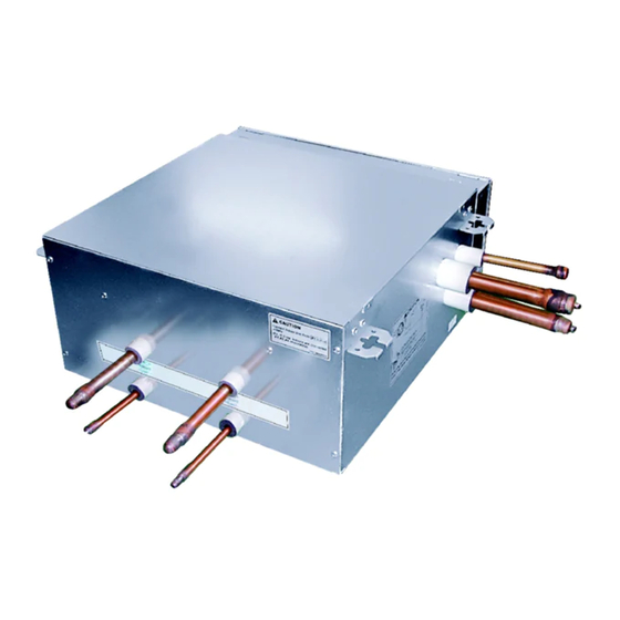
Features & Installation Part Features Connection Pipe (to outdoor unit) Control Box Coil assembly, Solenoid Connection Pipe (to outdoor unit) Connection Pipe (to indoor unit) Model PRHR021 PRHR031 PRHR041 Max. Connectable No. of Indoor Units Max. Connectable No. of Indoor Units of a branch Nominal Input Cooling Heating... -
Page 5: Installation
Installation Installation Selection of the best location n Select installation location of the HR unit suitable for following conditions • Avoid a place where rain may enter since the HR unit is for indoor. • Sufficient service space must be obtained. •... - Page 6 Installation HR Unit Installation • Select and mark the position for fixing bolts. • Insert the set anchor and washer onto the suspen- • Drill the hole for set anchor on the face of ceiling. sion bolts for locking the suspension bolts on the ceiling.
- Page 7 Installation CAUTION: HR Unit should be installed that top side is facing up. If not, it may cause failure of the product. Ceiling Top side Top side Top side WARNING: Before brazing work, remove gas in the HR Unit by cutting the three pipes in the small circles on the figure. If not, it may cause injuries.
- Page 8 Installation Thermal Insulation Insulate the connected pipes completely(all thermal insulation must comply with local requirement) Make sure that there is no clearance here Thermal insulator for refrigerant pipe(Local supply) Refrigerant pipe (Local supply) Overlap with thermal Thermal insulator for refrigerant pipe insulator for piping (Local supply) CAUTION:...
- Page 9 Installation Setup the switch of HR Unit 1. Main function of SW02M ON S/W Selection No.1 Method for addressing valves of an HR unit (Auto/Manual) No.2 Model of HR unit No.3 Model of HR unit No.4 Model of HR unit No.5 Valve group setting SW02M...
- Page 10 Installation WARNING • If you want to use a PRHR031 for 2 branches HR unit after closing the 3rd pipes, set the dip switch for 2 branches HR unit. • If you want to use a PRHR041 for 3 branches HR unit after closing the 4th pipes, set the dip switch for 3 branches HR unit. •...
- Page 11 Installation 3. SW01M/SW03M/SW04M (Dip S/W and tact S/W for manual valve addressing) 1) Normal setting (Non-Zoning setting) - Used in manual addressing of the valve in the HR unit - Set the address of the valve of the HR unit to the central control address of the connected indoor unit. - SW01M: selection of the valve to address SW03M: increase in the digit of 10 of valve address SW04M: increase in the last digit of valve address...
- Page 12 Installation 2) Zoning setting - Set the address of the valve of the HR unit to the central control address of the connected indoor unit. - SW01M : selection of the valve to address SW03M : increase in the digit of 10 of valve address SW04M : increase in the last digit of valve address SW05M :Rotary S/W - Prerequisite for manual valve addressing : central control address of each indoor unit must be preset...
-
Page 13: Coil Exchanging Method
Coil Exchanging Method Coil Exchanging Method 1. Remove the 2 securing screws. 2. Take out the connectors on the pcb. Remove the cover by pulling on the bottom of the Remove the 4 securing screws. cover and lifting up. Lay down the control box. 3. - Page 14 HR Unit...
- Page 15 [Representative] LG Electronics Inc. EU Representative Krijgsman 1, 1186 DM Amstelveen, The Netherlands [Manufacturer] LG Electronics Inc. Changwon 2nd factory 84, Wanam-ro, Seongsan-gu, Changwon-si, Gyeongsangnam-do, KOREA...
Need help?
Do you have a question about the PRHR Series and is the answer not in the manual?
Questions and answers