Advertisement
INSTALLATION MANUAL
AIR
CONDITIONER
Please read this installation manual completely before installing the product.
Installation work must be performed in accordance with the national wiring
standards by authorized personnel only.
Please retain this installation manual for future reference after reading it thoroughly.
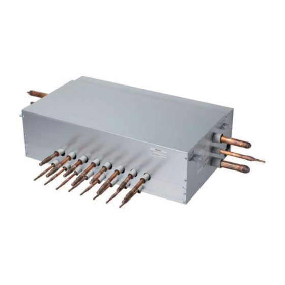
PRHR083/PRHR063/PRHR043/PRHR033/PRHR023 (Heat Recovery Unit)
Original instruction
[Representative] LG Electronics Inc. EU Representative : LG Electronics European Shared Service Center B.V.
Krijgsman 1, 1186 DM Amstelveen, The Netherlands
[Manufacturer] LG Electronics Inc. Changwon 2nd factory 84, Wanam-ro, Seongsan-gu, Changwon-si,
Gyeongsangnam-do, KOREA
MFL32987320
Rev.01_011719
Copyright © 2017 - 2019 LG Electronics Inc. All Rights Reserved.
www.lg.com
Advertisement
Table of Contents

Related Manuals for LG Multi V PRHR023


Summary of Contents for LG Multi V PRHR023
- Page 1 Please retain this installation manual for future reference after reading it thoroughly. PRHR083/PRHR063/PRHR043/PRHR033/PRHR023 (Heat Recovery Unit) Original instruction [Representative] LG Electronics Inc. EU Representative : LG Electronics European Shared Service Center B.V. Krijgsman 1, 1186 DM Amstelveen, The Netherlands [Manufacturer] LG Electronics Inc. Changwon 2nd factory 84, Wanam-ro, Seongsan-gu, Changwon-si, Gyeongsangnam-do, KOREA www.lg.com...
-
Page 2: Tips For Saving Energy
TIPS FOR SAVING ENERGY TIPS FOR SAVING ENERGY Here are some tips that will help you minimize the power consumption when you use the air conditioner. You can use your air conditioner more efficiently by referring to the instructions below: •... -
Page 3: Important Safety Instructions
IMPORTANT SAFETY INSTRUCTIONS IMPORTANT SAFETY INSTRUCTIONS READ ALL INSTRUCTIONS BEFORE USING THE APPLIANCE. Always comply with the following precautions to avoid dangerous situations and ensure peak performance of your product WARNING It can result in serious injury or death when the directions are ignored CAUTION It can result in minor injury or product damage when the... - Page 4 IMPORTANT SAFETY INSTRUCTIONS leakage, electric shock, or fire. • Always ground the product. - There is risk of fire or electric shock. • Make the connections securely so that the outside force of the cable may not be applied to the terminals. - Inadequate connection and fastening may generate heat and cause a fire.
- Page 5 IMPORTANT SAFETY INSTRUCTIONS CAUTION • Avoid a place where rain may enter since the HR unit is for indoor. - There is risk of property damage, failure of product, or electric shock. • Do not install a HR unit in a space where persons exists such as living room, office or meeting room with not only low but also open ceiling.
-
Page 6: Table Of Contents
TABLE OF CONTENTS TIPS FOR SAVING ENERGY IMPORTANT SAFETY INSTRUCTIONS FEATURES INSTALLATION PART INSTALLATION Selection of the best location Dimensional drawings HR Unit Installation Insulation Wiring Connection HR Unit PCB Setup the switch of HR Unit COIL EXCHANGING METHOD JOINT METHOD OF HR UNIT... -
Page 7: Features
FEATURES FEATURES Connection Pipe (to outdoor unit) Control Box Connection Pipe Connection Pipe (to indoor unit) (to outdoor unit) PRHR023 PRHR033 PRHR043 Model Max. Connectable No. of Indoor Units Max. Connectable No. of Indoor Units of a branch 39.8 Cooling [W] Nominal Input 37.2 Heating [W]... - Page 8 FEATURES Connection Pipe (to outdoor unit) Control Box Connection Pipe (to indoor unit) Connection Pipe (to outdoor unit) PRHR063 PRHR083 Model Max. Connectable No. of Indoor Units Max. Connectable No. of Indoor Units of a branch Cooling [W] 75.9 Nominal Input 72.1 Heating [W] 27.2...
-
Page 9: Installation Part
INSTALLATION PART INSTALLATION PART - Installation Manual - Hanging bolts (4 x M10 or M8), Nut(8 x M10 or M8), Flat washers(8 x M10) - Reducers [Unit : mm(inch)] Gas pipe MOD els Liquid pipe High pressure Low pressure OD 22.2(7/8) Ø 19.05(3/4) Ø 15.88(5/8) OD 19.05(3/4) Ø... -
Page 10: Installation
INSTALLATION INSTALLATION Selection of the best location Select installation location of the HR unit suitable for following conditions - Avoid a place where rain may enter since the HR unit is for indoor. - Sufficient service space must be obtained. - Refrigerant pipe must not exceed limited length. - Page 11 INSTALLATION PRHR063/PRHR083 [Unit : mm] 100 more (Serviceing space) 300 more 300 more (Servicing space) (Servicing space) 100 more Inspection door (Serviceing space) (servicing space) 450 more 300 more (Servicing space) (Servicing space)
- Page 12 INSTALLATION [Unit : mm] Description Part Name PRHR033/PRHR043 PRHR023 PRHR063/PRHR083 Low pressure Gas pipe Ø 28.58 Brazing connection Ø 22.2 Brazing connection connection port High pressure Gas pipe Ø 22.2 Brazing connection Ø 19.05 Brazing connection connection port Ø 15.88 Brazing connection Liquid pipe connection port Ø...
-
Page 13: Hr Unit Installation
INSTALLATION HR Unit Installation Using an insert-hole-in- anchor, hang the suspension bolt. - Select and mark the position for fixing bolts. Install a six-sided nut and a flat washer - Drill the hole for set anchor on the face of (locally-procured)to the suspension bolt as ceiling. - Page 14 INSTALLATION CAUTION HR Unit should be installed that top side is facing up. If not, it may cause failure of the product. Ceiling Top side Top side Top side WARNING Before brazing work, remove gas in the HR Unit by cutting the three pipes in the small circles on the figure.
- Page 15 INSTALLATION IMPORTANT! Please read this instruction sheet completely before installing the product. This air conditioning system meets strict safety and operating standards. As the installer or service person, it is an important part of your job to install or service the system so it operates safely and efficiently. WARNING •...
-
Page 16: Insulation
INSTALLATION Insulation Insulate the connected pipes completely(all thermal insulation must comply with local requirement) Make sure that there is no clearance here Thermal insulator for refrigerant pipe(Local supply) Overlap with thermal insulator for piping Refrigerant pipe (Local supply) Thermal insulator for refrigerant pipe (Local supply) CAUTION Insulate completely unconnected pipes as shown in the Figure. -
Page 17: Wiring Connection
INSTALLATION Wiring Connection Connect the wires to the terminals on the control board individually according to the outdoor unit connection. - Ensure that the color of the wires of outdoor unit and the terminal No. are the same as those of HR Unit respectively. -
Page 18: Hr Unit Pcb
INSTALLATION HR Unit PCB Branch No. Main PCB (2 EA, same P/No) Branch #1~4 Branch #5~8 Bypass Bypass (from left) SC EEV 7-SEG 7-SEG (from left) Branch #3,4 Branch #7,8 High/Low High/Low (from top) (from top) Branch #1,2 Branch #5,6 High/Low High/Low (from top) -
Page 19: Setup The Switch Of Hr Unit
INSTALLATION Setup the switch of HR Unit Function Selection of the method for pipe detection SW02E Selection of Master/Slave Main PCB (8pin DIP SW) Setting the Zoning Control Selection of the No. of connected branches SW01E Selection of the valve to address (4pin DIP SW) SW01D Selection of the Valve Group Control... - Page 20 INSTALLATION 1) Selection of the method for pipe detection of an HR unit (Auto/Manual) Auto Manual Switch No.1 Off Switch No.1 On Master Master * Master Only 2) Selection of Master/Slave Main PCB Master Slave Switch No.5 Off Switch No.5 On NOTE Do not turn on any SW02E on Slave Main PCB except No.5.
- Page 21 INSTALLATION 3) Setting the zoning control SW02E setting SW01E setting * Master Only Master Normal control SW01E * Master Only Master Master Turn the DIP switch of the zoning branch on. Zoning EX) Branch 1,2 are zoning control control. SW01E 4) Selection of the No.
- Page 22 INSTALLATION Main function of SW01D 1) Selection of the Valve Group Control NOTE Use the Valve Group Control when 2 branches are connected with only 1 indoor unit which has higher capacity than 61 kBTU. * Master Only SW01D SW01D Valve Group Valve Group Setting...
- Page 23 INSTALLATION SW01C (Rotary S/W for addressing HR unit) Must be set to '0' when installing only one HR unit. When installing multiple HR units, address the HR units with sequentially increasing numbers starting from '0'. Maximum 16 HR Units can be installed. Ex) Installation of 3 HR units * Master Only SW01B/SW01C/SW01E/SW02B...
- Page 24 INSTALLATION S/W No. Setup Manual addressing of valve #1 (Master) / #5 No.1 (Slave) Manual addressing of valve #2 (Master) / #6 No.2 (Slave) Manual addressing of valve #3 (Master) / #7 SW01E No.3 (Slave) Manual addressing of valve #4 (Master) / #8 No.4 (Slave) SW02B...
- Page 25 INSTALLATION 2) Zoning setting NOTE Use the Zoning Control when install two or more indoor units at 1 branch of HR Unit. The indoor units controlled by Zoning Control can be selected collectively as the cooling/heating mode. ex) Manual pipe detection of Valve #5 with three zoning indoor units, #6 without zoning unit. Slave Slave Slave...
-
Page 26: Coil Exchanging Method
COIL EXCHANGING METHOD COIL EXCHANGING METHOD Remove the 2 securing screws. Remove the 6 securing screws. Remove the cover by pulling on the bottom Lift up and pull on the cover. of the cover and lifting up. Lift up and pull on the insulator. Exchange the coil. -
Page 27: Joint Method Of Hr Unit
JOINT METHOD OF HR UNIT JOINT METHOD OF HR UNIT Joint Method is required when use indoor unit that exceed 61 kBtu is installed. In Joint Method, two neighboring outlets of one HR unit are linked by Y branch pipe and connected to one indoor unit.
Need help?
Do you have a question about the Multi V PRHR023 and is the answer not in the manual?
Questions and answers