Furrion Vision S Instruction Manual
5“ and 7” camera system
Hide thumbs
Also See for Vision S:
- User manual (108 pages) ,
- Instruction manual (26 pages) ,
- Installation manual (11 pages)
Table of Contents
Advertisement
5" and 7" Vision S Camera System
Système de caméra Vision S de 5 et 7 po
Sistema de cámara Vision S de 5" y 7"
Instruction Manual
Manuel d'instructions
Manual de instrucciones
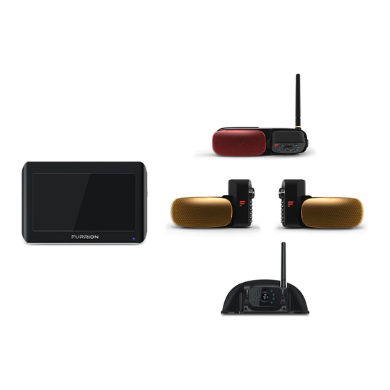
* The packing contents may be different based on the kit you purchased.
Please take the actual product as standard.
* Le contenu de l'emballage peut être différent en fonction de la trousse
achetée. Veuillez prendre le produit réel en référence.
* Es posible que los contenidos del embalaje sean diferentes según el kit
que haya comprado. Tome el producto real como estándar.
Models: FOS07TASK/FOS07TASR/FOS07TASE/FOS07TASF
FOS07TAEK/FOS07TAED/FOS07TAPK/FOS07TAPT
FOS05TASK/FOS05TASR/FOS05TASE/FOS05TASF
FOS05TAEK/FOS05TAED/FOS05TAPK/FOS05TAPT
Model: FCD48TASF
Advertisement
Table of Contents

Related Manuals for Furrion Vision S


Summary of Contents for Furrion Vision S
- Page 1 5“ and 7” Vision S Camera System Système de caméra Vision S de 5 et 7 po Sistema de cámara Vision S de 5” y 7” Instruction Manual Manuel d’instructions Manual de instrucciones Model: FCD48TASF * The packing contents may be different based on the kit you purchased.
-
Page 2: Welcome
Welcome ® Thank you for purchasing this Furrion Vision S Camera System. Before operating your new product, please read these instructions carefully. This instruction manual contains information for safe use, installation and maintenance of the product. Please keep this instruction manual in a safe place for future reference. This will ensure safe use and reduce the risk of injury. -
Page 3: Table Of Contents
Contents Welcome ....................2 Contents ....................3 Important Safety Instructions............4 .................. 5 FCC Statement IC Statement ......................6 Product Overview ................7 Product Description ....................7 Monitor ........................7 Left/Right Camera ....................8 Front/Rear Camera ....................8 Installation ..................9 What’s in the Box ....................9 Monitor Installation....................9 Camera Installation ....................11 Installation ..................11 Electrical Connections ....................16 Getting Started ..................18... -
Page 4: Important Safety Instructions
Installation warranty. Furrion is not liable in full or in Installation and wiring of this product part for improper installation resulting require specialist skills. To ensure proper... -
Page 5: Fcc Statement
Important Safety Instructions NOTE: The Grantee is not responsible for any changes or modifications not expressly Electrical appliances and overhead power approved by the party responsible for lines can affect the wireless signal. compliance. Such modifications could Do not place the monitor in a location void the user’s authority to operate the where it might hinder field of vision while equipment. -
Page 6: Ic Statement
Important Safety Instructions IC Statement This device complies with Industry Canada licence-exempt RSS standard(s). Operation is subject to the following two conditions: (1) this device may not cause interference, and (2) this device must accept any interference, including interference that may cause undesired operation of the device. -
Page 7: Product Overview
Product Overview Product Description The Furrion Vision S Camera System is designed to assist the driver by providing a clear and wide image of the area behind the vehicle whenever the vehicle is shifted into reverse. Never rely solely on this product to ensure the area is clear of children and/or obstructions. Use your monitor and look both ways. -
Page 8: Left/Right Camera
Product Overview Left/Right Camera Traffic Light Lens 12 IR LED Light Monitor Pairing Button Light Sensor LED Indicator Front/Rear Camera Traffic Light Light Sensor Antenna Lens Monitor Pairing Button LED Indicator 8 IR LED... -
Page 9: Installation
Installation COMPLETELY READ THIS MANUAL BEFORE 2. Mark a basic outline on the wall using the INSTALLATION provided mounting bracket. (Fig. 1) NOTE: We have included all of the items needed for most standard installations, but all vehicles are different. We recommend you review your vehicle completely before starting. - Page 10 5. Fix the mounting bracket onto the vehicle wall using 2 flat self-tapping screws provided. (Fig. 4) NOTE: Make sure the “FURRION VISION S” is facing up while installing. Fig. 1 3. Align the dot bullet of the tabletop bracket with the opening on back of the monitor and push firmly until locked into place.
-
Page 11: Camera Installation
Installation Where practical, as high as possible at the rear of the vehicle. Horizontal-center of the vehicle or as close as is optimal. Mount camera at least 2 inches above or below running lights. Close proximity to lights may cause image blooming, blurring and reduced night vision performance. - Page 12 Installation ” Good Signal Fig. 11 3. Feed the supplied 6-foot camera power cable through the gasket. Ensure the bare end of the cable goes into the vehicle and the flat side faces inward. (Fig. 12) Poor Signal Doorway Camera Installation (if Camera Power Bracket purchased)
- Page 13 Installation 6. If only installing the mounting bracket, 9. Connect the camera power cable to the secure the camera power cable inside the camera cable. (Fig. 17) mounting and attach the cover. (Fig. 14) Fig. 17 Fig. 14 10. Place the attached cables and 7.
- Page 14 (if purchased) A traffic light must be installed together with the camera. For best performance, we recommend a Furrion traffic light is selected. 1. Select a suitable position on the side of the vehicle wall where you would like to install the camera.
- Page 15 (if purchased) A traffic light must be installed together with the camera. For best performance, we recommend a Furrion traffic light. 1. Select a suitable position on front or back of the vehicle wall that you would like to install the camera.
- Page 16 Installation 3. Remove the two screws holding the decorative part using a Phillips screwdriver and set aside. (Fig. 30) Fig. 33 Fig. 30 4. Pull to remove the decorative part from traffic light and save in a safe place in case of future use.
-
Page 17: Electrical Connections
Installation 8. Repeat steps 1 to 7 to install the other The Furrion Vision S Camera System can be camera. connected to an electrical power source via a 7 Way Connector. Electrical Connections Wiring to running lights: the camera will... -
Page 18: Getting Started
Getting Started Pairing the Camera and Monitor The camera and monitor need to be paired the first time you are using your Vision S Camera System. 1. Touch PAIRING on screen. The PAIRING NOTE: Ensure both the camera and monitor... - Page 19 Getting Started 3. Once paired successfully, a red icon 4. An icon indicates pairing failed, repeat will appear after the device list. steps 2 and 3 to pair again. 5. Repeat steps 1 to 4 to pair the other cameras. 6.
-
Page 20: Change Settings
Change Settings Camera Setting 3. Press DOOR, LEFT, RIGHT or REAR to enable or disable one or more camera(s) as auto displaying camera(s) when using Touch SETUP on screen. The SETUP will be the wireless vehicle rear observation highlighted in red once selected and enter system. - Page 21 Change Settings 3. Touch to set the camera image rotation AUTO DIM SETTING angle as NORMAL (0 ), ROTATE (90 ), FLIP 1. Touch AUTO DIM on screen to enter the (180 ) or FLIP and ROTATE (270 submenu. 4. Repeat steps 2 and 3 to set the other camera.
- Page 22 Change Settings LCD AUTO OFF SETTING MOTION DETECT SETTING 1. Touch LCD AUTO OFF on screen to enter The motion detect function is used to the submenu. detect objects in motion and assist in safe driving while the vehicle is in reverse. When on, the monitor LCD will be illuminated automatically when motion is detected.
-
Page 23: Picture Setting
Change Settings Picture Setting 4. Press to change the settings. 1. Touch PICTURE on screen. The PICTURE will be highlighted in red once selected and enter the submenu automatically. 5. Repeat steps 2 to 4 to change the other camera(s) settings. Software Version 2. -
Page 24: Operation
Operation Operating the System The Wireless Vehicle Rear Observation System operates when the vehicle is shifted into reverse. The Camera transmits a clear When in quadrant mode: and wide image with Audio from the area 1. Touch the center of the monitor screen to behind the vehicle to the monitor inside the show the icon. - Page 25 Operation Press twice on the monitor screen to show When in single channel mode: Press once on the monitor screen to enter the menu of control. the camera selection interface. Icon Description Icon Description Press to return to the quad- Press to turn On/Off the on- rant mode.
-
Page 26: Care And Cleaning
Care and Cleaning Though your monitor requires little care, you will still need to maintain its condition and performance by following the guidelines below. Keep your system away from excessive moisture, extreme heat or cold. Keep liquids away from the display. Occasionally clean the surface of the monitor with a soft cloth moistened with water or glass cleaner. -
Page 27: Specifications
Specifications Specifications SUPPLY VOLTAGE DC8 to 30V WIRELESS FREQUENCY 2.4 GHz WIRELESS RANGE 150m (open area) TRANSMITTING SPEED 6 Mbps (single) RECEIVING SENSITIVITY -88 +/-3dBm DECOMPRESSION FORM H.264 DELAYING TIME <250ms CAMERA IMAGE DISTANCE Rear: <5m / Side: <12m CMOS SIZE 1⁄3”... -
Page 28: Troubleshooting
Troubleshooting Problem Solution Check the power cable is connected. Monitor won’t turn on (no Check the cigarette lighter has 12-24V DC Output. blue LED) Check the fuse in the cigarette socket adapter. Check if the camera is receiving power. Camera and Monitor won’t pair Make sure to hold the camera pairing button for 2 seconds. -
Page 29: Warranty
Warranty FURRION WARRANTS FOR A PERIOD OF 1 YEAR FROM DATE OF RETAIL PURCHASE BY THE ORIGINAL END-USE PURCHASER, THAT THIS PRODUCT, WHEN DELIVERED TO YOU IN NEW CONDITION, IN ORIGINAL PACKAGING, FROM A FURRION AUTHORIZED RESELLER AND USED IN NORMAL CONDITIONS, IS FREE FROM ANY DEFECTS IN MANUFACTURING, MATERIALS, AND WORKMANSHIP. - Page 30 DOWNTIME, GOODWILL, DAMAGE TO OR REPLACEMENT OF ANY EQUIPMENT OR PROPERTY, ANY COSTS OF RECOVERING, REPROGRAMMING, OR REPRODUCING ANY PROGRAM OR DATA STORED IN OR USED WITH FURRION PRODUCTS. FURRION’S TOTAL LIABILITY IS LIMITED TO THE REPAIR OR REPLACEMENT OF THIS PRODUCT PURSUANT TO THE TERMS OF THIS WARRANTY.
- Page 31 Veuillez aussi remettre le présent manuel à tout nouveau propriétaire de cet appareil. Le fabricant décline toute responsabilité en cas de dommages dus au non-respect des présentes consignes. Si vous avez des questions sur nos produits, veuillez nous contacter : support@furrion.com...
- Page 32 “Contains Transmitter Module FCC ID: 2ABH3-FCX48TA” “Contains Transmitter Module IC: 23337-FCX48TA” This device complies with part 15 of the FCC Rules. Operation is subject to the following two conditions: (1) This device may not cause harmful interference, and (2) this device must accept any interference received, including interference that may cause undesired operation.
Need help?
Do you have a question about the Vision S and is the answer not in the manual?
Questions and answers
My system turns off after a few minutes and does not automatically switch to left or right when the signal is activated. Nor does it automatically switch to rear camera when the tow vehicle is put into reverse.