Table of Contents
Advertisement
Quick Links
FORWARD .................................................................................................................................................................. 2
INTRODUCTION ....................................................................................................................................................... 3
......................................................................................................................................................... 3
SAFETY INSTRUCTIONS ........................................................................................................................................ 4
................................................................................................................................................. 4
................................................................................................................................................ 6
OPERATING INSTRUCTIONS .............................................................................................................................. 10
TRANSPORTATION ............................................................................................................................................... 13
WEAR PARTS ........................................................................................................................................................... 13
MAINTENANCE....................................................................................................................................................... 14
PARTS LISTS ............................................................................................................................................................ 16
LINERS AND SEALS ............................................................................................................................................ 16
FRONT END ASSEMBLY .................................................................................................................................... 17
MAJOR WELDMENTS ......................................................................................................................................... 19
BACK END ASSEMBLY ...................................................................................................................................... 20
BLAST WHEEL ASSEMBLY ............................................................................................................................... 21
GENERAL ASSEMBLY ........................................................................................................................................ 23
TROUBLESHOOTING ............................................................................................................................................ 25
ELECTRICAL SCHEMATIC ................................................................................................................................. 26
BP-10 SUPER Table of Contents
................................................................................................................................... 4
........................................................................................................................ 8
...................................................................................................................... 8
.................................................................................................................. 9
........................................................................................................................................ 11
........................................................................................................ 14
............................................................................................................................ 15
1
Advertisement
Table of Contents

Related Manuals for BlastPro BP-10 SUPER


Summary of Contents for BlastPro BP-10 SUPER
-
Page 1: Table Of Contents
BP-10 SUPER Table of Contents FORWARD .................................. 2 INTRODUCTION ............................... 3 ................................. 3 PECIFICATIONS SAFETY INSTRUCTIONS ............................4 — G ..............................4 AFETY ENERAL — S ........................... 4 AFETY SSESSMENT — S ..............................6 ... -
Page 2: Forward
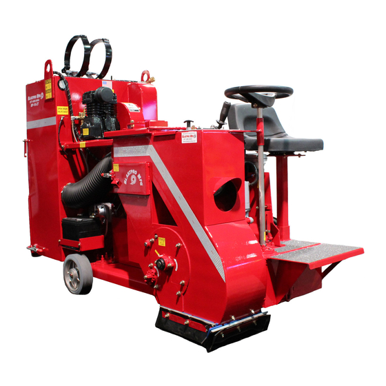
Forward Thank you for your purchase of a shotblasting machine from BlastPro Manufacturing, Inc. We feel that you have purchased the highest quality shotblasting equipment on the market today. This manual has been prepared to give the operator a general understanding of the machine. It is not intended to be an all encompassing document which addresses every situation which may be encountered when operating the machine. -
Page 3: Introduction
S-280 to S-460. Wear parts are interchangeable with BLASTRAC parts. The mechanics of the BP-10 SUPER are fairly simple. When the shot lever is opened, a cable connected to the shot lever opens the shot valve which subsequently allows shot from the shot hopper to be released. -
Page 5: Safety Instructions
Safety Instructions ALL OPERATORS AND MAINTENANCE PERSONNEL SHOULD READ THIS SECTION CAREFULLY BEFORE OPERATING OR MAINTAINING THIS EQUIPMENT. THESE SAFETY INSTRUCTIONS ARE NOT MEANT TO REPRESENT AN ALL-INCLUSIVE LIST OF INSTANCES WHICH COULD OCCUR WHEN OPERATING THIS EQUIPMENT. FOR, AS WITH ANY PIECE OF CONSTRUCTION EQUIPMENT, SERIOUS INJURY CAN OCCUR IF PROPER SAFETY PROCEDURES ARE NOT DILIGENTLY FOLLOWED. - Page 6 WITH DANGEROUS MATERIALS. THE CONTRACTOR IS RESPONSIBLE, FURTHERMORE, FOR PROTECTING ALL WORKERS FROM BEING EXPOSED TO DANGEROUS MATERIALS. SO, BECAUSE THE BP-10 SUPER SHOTBLASTING MACHINE HAS NOT BEEN DESIGNED TO REMOVE, CLEAN, PROFILE, OR ALTER ANY SURFACE COATED WITH OR OTHERWISE CONTAMINATED BY DANGEROUS MATERIALS, BLASTPRO MANUFACTURING, INC.
-
Page 7: Safety - Start Up
Inspect all electrical cords on the BP-10 SUPER for damage, tears, or other signs of wear. If electrical cords are damaged, then do not attempt to perform blasting operations until cords have been repaired or replaced. - Page 8 BP-10 SUPER throws shot which could present a serious danger if the shot hopper door is not properly closed. Make certain that the blast seals of the BP-10 SUPER are not worn out. As these seals provide the suction that is required by the machine, they will become dislodged if they become worn out.
-
Page 9: Safety - Operation Procedures
Advance the machine until you are sure that no deep holes are being blasted into the surface. Turn off the breakers to the BP-10 SUPER and to the dust collector. Turn switch on the BP-10 SUPER and dust collector to the OFF position. -
Page 10: Safety - Maintenance Procedures
Empty all shot from the shot hopper on the BP-10 SUPER. Shot should never be left in BP-10 SUPER after work is performed. Never move or transport BP-10 SUPER with shot in the shot hopper as this may result in damage to the equipment. -
Page 11: Operating Instructions
12. After verifying proper suction, reconnect the hose to the BP-10 SUPER. 13. Check the seals on the BP-10 SUPER to verify that the seals are set at the proper height. The seals should be rubbing the surface of the concrete or steel. -
Page 12: Setting Control Cage
Setting the correct blast pattern is essential before an even, clean profile can be achieved when shot blasting with a BlastPro Manufacturing machine. An uneven blast pattern can leave shadows on either side of the floor surface and can cause premature wear to the internal components. - Page 13 5. The initial setting of a machine rotating in a counter-clockwise direction should be between 8:30 and 10:30 as indicated in Figures B and C. The resultant-cleaning path will determine the final setting. These settings will vary with the abrasive size and the surface being cleaned. Once the proper control cage setting is obtained, the blast pattern should remain consistent.
-
Page 14: Transportation
As a result, the operator or maintenance personnel should inspect the BP-10 SUPER wear parts prior to operation and change the parts as necessary. Wear parts and inspection times, other than inspection prior to use, on the BP-10 SUPER are listed below:... -
Page 15: Maintenance
16. Verify that all nuts are tight and secure 17. Briefly activate the grinder motor to verify good balance and proper clearance. Note: Only blast wheels manufactured by BlastPro Manufacturing, Inc. should be used by the BP-10 SUPER. Other blast wheels that have not been tested by BlastPro... -
Page 16: General Maintenance Points
Greasing the Bearing Unit The bearing unit is located on the back of the blast housing. The unit must receive regular lubrication to operate properly. Blastpro Manufacturing recommends using Mobil Polyrex EM grease. There are grease fittings at both ends of the bearing unit. Each fitting should receive several pumps of grease. -
Page 17: Parts Lists
PARTS LISTS LINERS AND SEALS ITEM QUANTITY PART DESCRIPTION NUMBER NUMBER BT4899470_ LEFT LINER 10D BT4899460_ TOP LINER BT4900450_ SIDE REBOUND 10D BT4899490_ BOTTOM REBOUND PLENUM LINER BT4899480 RIGHT LINER 10D BT4900440_ TOP REBOUND LINER BT4899450 INSULATOR/MAGNET SIDE BT4813500 SPACER/INSULATOR BT4900470_ SIDE MAGNET BT4900490_... -
Page 18: Front End Assembly
FRONT END ASSEMBLY... - Page 19 ITEM QUANTITY PART DESCRIPTION NUMBER NUMBER BT4899430_A PLENUM 1-10D BT4900780-AC SUPPORT DRIVE YOKE/AC DRIVE DRIVE BT4919500 YOKE BT4919490_ ARM/LINKAGE BT4919480_ LINKAGE FRONT END ASSEMBLY BT4900760-AC DRIVE HANDLE BT4532900 GRIP/ HANDLE 1.00" ID RUBBER BT4900740_ LEVER FOR HANDLE BT2055710 3/4" 2 BOLT FLG BEARING 1-10D BT4900720-AC SHAFT/FRONT WHEEL BT4776290 HUB TRACTION DRIVE...
-
Page 20: Major Weldments
MAJOR WELDMENTS ITEM QUANTITY PART DESCRIPTION NUMBER NUMBER BT4899400 BLAST HOUSING 1-10D BT4899430_A PLENUM 1-10D BT4895410 SEPARATOR BT4900560_A DEFLECTOR SEPERATOR BT4900680_A LID SHOT HOPPER 1-10D BT4917670_A BLAST WHEEL MOTOR MOUNT... -
Page 21: Back End Assembly
BACK END ASSEMBLY ITEM QUANTITY PART DESCRIPTION NUMBER NUMBER BT4899400 BLAST HOUSING 1-10D BT4917670_A BLAST WHEEL MOTOR MOUNT BT6997050 3V 3GR 6.50 SHEAVE BT4932650_B 2517 T/L BUSHING BT6997040 3V 3GR 3.65" PULLEY BT6997040-1 1610 T/L BUSHING BT4917440 BACK PLATE BT4932630-1 3VX BELT BT4892950 BEARING UNIT... -
Page 22: Blast Wheel Assembly
BLAST WHEEL ASSEMBLY... - Page 23 ITEM QUANTITY PART DESCRIPTION NUMBER NUMBER BT4899400 BLAST HOUSING 1-10D BT4959410 CONTROL CAGE BRKT BT4959420 SUPPORT/BRKT CONTROL CAGE BT4892950 BEARING UNIT BT6800200_ SHOT VALVE BT4936980 ADAPTER/FEED SPOUT BT4959400_A BLAST WHEEL HUB BT4959400-1 BLAST WHEEL HUB PINS BT4784610_ SHOT VALVE LINKAGE BT4146990 CLAMP/CONTROL CAGE BT4937000...
-
Page 24: General Assembly
GENERAL ASSEMBLY... - Page 25 ITEM QUANTITY PART DESCRIPTION ITEM QUANTITY PART DESCRIPTION NUMBER NUMBER NUMBER NUMBER BT4899400 BLAST HOUSING 1-10D BT4919680 CLEVIS PIN BT4900450_ SIDE REBOUND 10D BT6796740_S SKID SEAL KID SEAL BT4899430_A PLENUM 1-10D BT4146990 CLAMP/CONTROL CAGE BT4895410 SEPARATOR BP4939650 FEED SPOUT CLAMP-BP BT4900600 BLASTHOUSING COVER BT4900500...
-
Page 26: Troubleshooting
Troubleshooting Increased cleaning time. Improper abrasive feed to Check ammeter reading. Low reading wheel. indicates insufficient abrasive getting to wheel. Storage hopper. Check abrasive level. Contaminated abrasive. Abrasive may contain substantial percentage of fines and contaminants. Check ventilation. Abrasive feed and abrasive Check for obstructions in the abrasive control valve. -
Page 27: Electrical Schematic
Electrical Schematic...
Need help?
Do you have a question about the BP-10 SUPER and is the answer not in the manual?
Questions and answers