Table of Contents
Advertisement
Quick Links
X 1
X 2
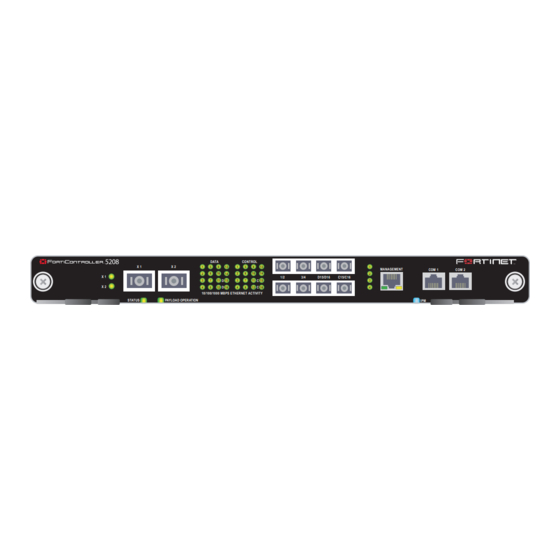
A detailed guide to the FortiController-5208 module. This document describes the module LEDs and connectors,
describes how to install the module in a FortiGate-5000 series chassis, and contains a brief troubleshooting section
to help you diagnose and fix problems with the module.
The most recent versions of this and all FortiGate-5000 series documents are available from the
page of the
Fortinet Technical Documentation
Visit
http://support.fortinet.com
FortiController-5208 System Guide
01-30000-0376-20070615
DATA
X 1
X 2
1
5
9
13
2
6
10
14
3
7
11
D
15
D
4
8
12
16
10/100/1000 MBPS ETHERNET ACTIVITY
PAYLOAD OPERATION
STATUS
web site (http://docs.forticare.com).
to register your FortiController-5208 system. By registering you can receive product
updates, technical support, and FortiGuard services.
www.fortinet.com
S y s t e m G u i d e
FortiController-5208
CONTROL
1
5
9
13
2
6
10
14
1/2
3/4
D15/D16
C15/C16
3
7
11
C
15
C
4
8
12
16
1
MANAGEMENT
COM 1
COM 2
2
3
4
IPM
FortiGate-5000
Advertisement
Table of Contents

Related Manuals for Fortinet FortiController FortiController-5208


Summary of Contents for Fortinet FortiController FortiController-5208
- Page 1 The most recent versions of this and all FortiGate-5000 series documents are available from the page of the Fortinet Technical Documentation Visit http://support.fortinet.com to register your FortiController-5208 system. By registering you can receive product updates, technical support, and FortiGuard services.
-
Page 2: About This Guide
If the extraction levers become bent or damaged the FortiController-5208 module may not align correctly in the chassis slot. FortiGate page of the Fortinet Knowledge Center. Fortinet Fortinet Technical... -
Page 3: Table Of Contents
Contents Contents About this guide... 2 FortiController-5208 module ... 5 Hardware installation... 9 FortiController-5208 Firmware... 17 For more information... 27 FortiController-5208 System Guide 01-30000-0376-20070615... - Page 4 Contents FortiController-5208 System Guide 01-30000-0376-20070615...
-
Page 5: Forticontroller-5208 Module
FortiController-5208 module FortiController-5208 module You can create a FortiGate-5005-DIST high-throughput multi-threat network security system using one or two FortiController-5208 modules and multiple FortiGate-5005 modules in a FortiGate-5050 or FortiGate-5140 chassis. A FortiGate-5020 chassis cannot be used to create a FortiGate-5005-DIST system. -
Page 6: Front Panel Leds And Connectors
Front panel LEDs and connectors Front panel LEDs and connectors LEDs • Inserting a FortiController-5208 module into a chassis • Removing a FortiController-5208 module from a chassis • Troubleshooting From the FortiController-5208 front panel you can view the status of the module LEDs to verify that the module is functioning normally. - Page 7 FortiController-5208 module Table 1: FortiController-5208 module LEDs (Continued) CONTROL 1, 2, 3, 4 MANAGEMENT Link The control LEDs of a secondary FortiController-5208 module will be synchronized to the control LEDs of the primary because all the installed modules use the same fabric backplane network to communicate. Each FortiController-5208 module has its own base backplane network with which to exchange data traffic with the worker modules so the data LEDs of each FortiController-5208 module will indicate only its own communication.
- Page 8 Backplane gigabit interfaces Backplane gigabit interfaces Table 2: FortiController-5208 connectors (Continued) Connector Type Speed 1, 2, 3, 4 LC SFP 1000 Mbps Ethernet D15, D16 LC SFP 1000 Mbps Ethernet C15, C16 LC SFP COM1, COM2 RJ-45 9600 bps MANAGEMENT RJ-45 1000 Mbps Ethernet The FortiController-5208 module uses the chassis backplane gigabit interfaces for all communication with modules installed in the chassis.
-
Page 9: Hardware Installation
Hardware installation Hardware installation Before use, the FortiController-5208 module must be correctly inserted into a FortiGate-5140 or FortiGate-5050 chassis. XFP and SFP transceivers must also be installed before the module can be connected to other network devices. This chapter describes: •... - Page 10 Inserting a FortiController-5208 module into a chassis Inserting a FortiController-5208 module into a chassis Attach the ESD wrist or ankle strap to your wrist or ankle and to an ESD socket or to a bare metal surface on the chassis or frame. Remove the caps from XFP and SFP cage sockets on the FortiController-5208 front panel.
-
Page 11: Insertion Procedure
Hardware installation You can install the XFP and SFP transceivers into the FortiController-5208 front cage slots either before or after installing the module into a chassis. See “Installing XFP and SFP transceivers” on page Module placement When assembling a FortiGate-5005-DIST system, module placement is important. - Page 12 Inserting a FortiController-5208 module into a chassis Unlock the left and right extraction levers by squeezing the extraction lever locks. Unlock Extraction Lever Open the left and right extraction levers to their fully open positions. Alignment Pin Extraction Open Lever Lock Insert the FortiController-5208 module into the empty slot in the chassis.
- Page 13 Hardware installation If the chassis is powered on, as the module slides into place the IPM LED starts flashing blue. If the module is aligned correctly, inserted all the way into the slot, and the extraction levers are properly locked the IPM LED flashes blue for a few seconds.
- Page 14 Removing a FortiController-5208 module from a chassis To complete this procedure, you need: • A FortiGate-5140 or FortiGate-5050 chassis with a FortiController-5208 module installed • An electrostatic discharge (ESD) preventive wrist or ankle strap with connection cord Caution: The FortiController-5208 modules must be protected from static discharge and physical shock.
-
Page 15: Troubleshooting
If the BIOS starts up, interrupt the BIOS startup and install a new firmware image. For details about installing a new firmware image in this way, see CLI” on page If this does not solve the problem, contact Fortinet Technical Support. FortiController-5208 System Guide 01-30000-0376-20070615 Alignment Pin... - Page 16 Troubleshooting Hardware installation FortiController-5208 System Guide 01-30000-0376-20070615...
-
Page 17: Forticontroller-5208 Firmware
FortiController-5208 Firmware FortiController-5208 Firmware Fortinet periodically updates the FortiController-5208 firmware to include enhancements and address issues. After you have registered your FortiController-5208, firmware is available for download at the support web site, http://support.fortinet.com. Only the FortiController-5208 admin user can change the firmware. - Page 18 Reverting the FortiController-5208 to a previous firmware version Upgrading the firmware using the CLI Reverting the FortiController-5208 to a previous firmware version Reverting to a previous firmware version using the web-based manager To use the following procedure, you must have a TFTP server available on a network connected to the FortiController-5208 module management interface.
-
Page 19: Reverting To A Previous Firmware Version Using The Cli
FortiController-5208 Firmware Before beginning this procedures, it is recommended that you back up the FortiController-5208 module configuration. If you are reverting to a previous firmware version, you might not be able to restore the previous configuration from the backup configuration file. Note: To use this procedure, you must log in using the admin administrator account, or an administrator account that has system configuration read and write privileges. -
Page 20: Installing Firmware Images From A System Reboot Using The Cli
Installing firmware images from a system reboot using the CLI Installing firmware images from a system reboot using the CLI Make sure the FortiController-5208 module can connect to the TFTP server. You can use the following command to ping the computer running the TFTP server. - Page 21 FortiController-5208 Firmware • Install a TFTP server that you can connect to from the FortiGate internal interface. The TFTP server should be on the same subnet as the internal interface. Before beginning this procedure, it is recommended that you back up the FortiController-5208 module configuration If you are reverting to a previous firmware version, you might not be able to restore the previous configuration from the backup configuration file.
-
Page 22: Restoring The Previous Configuration
Installing firmware images from a system reboot using the CLI Restoring the previous configuration Type I and the Configuration and information menu is displayed: [S]: Set serial port baudrate(will take effect on next boot). [T]: Set image download port. [C]: Set DHCP enable (will take effect on next boot). -
Page 23: Testing A New Firmware Image Before Installing It
FortiController-5208 Firmware config system interface After changing the interface address, you can access the FortiController-5208 module from the web-based manager and restore the configuration. If you are reverting to a previous firmware version, you might not be able to restore the previous configuration from the backup configuration file. Testing a new firmware image before installing it You can test a new firmware image by installing the firmware image from a system reboot and saving it to system memory. - Page 24 Testing a new firmware image before installing it Enter the following command to restart the FortiController-5208 module. execute reboot The FortiController-5208 module responds with the following message: This operation will reboot the system! Do you want to continue? (y/n) Type y. As the FortiController-5208 module starts, a series of system startup messages is displayed.
- Page 25 FortiController-5208 Firmware Type the address of the TFTP server and press Enter: The following message appears: Enter Local Address [192.168.1.188]: Type an IP address the FortiController-5208 module can use to connect to the TFTP server. The IP address can be any IP address that is valid for the network the interface is connected to.
- Page 26 Testing a new firmware image before installing it FortiController-5208 Firmware FortiController-5208 System Guide 01-30000-0376-20070615...
-
Page 27: For More Information
Fortinet Tools and Documentation CD All Fortinet documentation is available from the Fortinet Tools and Documentation CD shipped with your Fortinet product. The documents on this CD are current for your product at shipping time. For the latest versions of all Fortinet documentation see the Fortinet Technical Documentation web site at http://docs.forticare.com. - Page 28 © Copyright 2007 Fortinet, Inc. All rights reserved. No part of this publication including text, examples, diagrams or illustrations may be reproduced, transmitted, or translated in any form or by any means, electronic, mechanical, manual, optical or otherwise, for any purpose, without prior written permission of Fortinet, Inc.
Need help?
Do you have a question about the FortiController FortiController-5208 and is the answer not in the manual?
Questions and answers