Table of Contents
Advertisement
Quick Links
Advertisement
Table of Contents

Related Manuals for Gossen MetraWatt SECUTEST SI+


Summary of Contents for Gossen MetraWatt SECUTEST SI+
- Page 1 Operating Instructions SI+ SECUTEST 3-349-613-15 1/12.10...
- Page 2 Standard Equipment 1 Input and memory module SECUTEST SI+, SECUTEST 1 USB connector cable, 1 Operating instructions The Driver Control software for installing without Function the USB device driver is available from MENU our website. GMC-I Messtechnik GmbH...
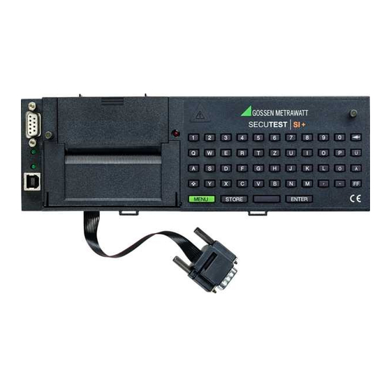
- Page 3 1 Ribbon cable with RS232 plug for connection of the SI module to the tester 12 Shift key to shift the keyboard from small letters to capital letters and vice versa shifts to full stop ( 2 USB socket connector for the transmission of stored data to the PC shifts to underline ( _ ) 3 LED signal lights up green when USB interface is active 13 Key...
-
Page 4: Table Of Contents
Contents Page Page Applications ................. 6 How to Display and Store Reports ..........12 Application SECUTEST.................6 How to Display Reports, Enter and Store Texts ..........12 Application PROFITEST 204 and METRISO 5000 D-PI ........7 Automatic Report Storage ................. 14 Meaning of the Symbols on the Unit .............7 Quick Report Storage ................ - Page 5 Contents Page Page Error Message ................21 Technical Data ................22 Maintenance ................25 11.1 How to Reset the SI Module ..............25 11.2 Housing ....................25 11.3 Device Return and Environmentally Compatible Disposal ......25 Repair and Replacement Parts Service ........26 Product Support ................
-
Page 6: Applications
Applications Note The SI (Storage Interface) module SECUTEST is a special accessory Transmission of the data from the memory of the SI module to the PC via the RS232 interface is only possible when the SI for the the following test instruments: module is connected to the test instrument. -
Page 7: Application Profitest 204 And Metriso 5000 D-Pi
USB Device Driver Application PROFITEST 204 and METRISO 5000 D-PI Operation with these test instruments is limited to the function „Entry of The Driver Control software for installing the USB device driver including comments via the alphanumeric keyboard.“ Only the following chap- the operating instructions are available for download from our website ters are relevant in this context: chap. -
Page 8: Safety Features And Safety Precautions
Safety Features and Safety Precautions When the SECUTEST is properly used, the safety of both the user Data Backup (only instruments of the SECUTEST... series) and the unit is assured. In order to meet the legal regulations for electromagnetic compatibility (EMC), an electrically conductive plastic material is used for the housing The measurement, report and entry data can be safely stored in the for shielding. -
Page 9: Getting Started
Getting Started Attention! Installing the SI Module As long as the signal lamp lights up at the SI module, a syn- Ð SECUTEST... only: Remove the cover from the lid of the SECUTEST..chronization between the test instrument and the SI module For this purpose, press the cover to the side. -
Page 10: Presettings
Request menu Presettings Upon selection of the menu item „Setup“ Press 1x MENU you can perform the following settings: Selection and execution of the functions listed in the menu is done by means of the corresponding keys on the test instrument. The other operating controls and connectors should remain unchanged while the SI mod- ule is active so that the data traffic will not be... -
Page 11: Enter And Delete Top And Bottom Lines
Ð You will get to the next line by pressing the Enter and Delete Top and Bottom Lines ENTER Ð You can delete the top and bottom lines with the keys Clear Memory To clear the memory, press the ENTER on the SI module. -
Page 12: How To Display And Store Reports
How to Display and Store Reports The test report automatically contains the test result including the measured and limit values as well as information on the visual inspec- Note tion. Further specific information on device under test, customer and Storage of the results of the safety and function tests as well as their repair can be integrated in the test report by entries via the keyboard or a entry into reports and statistics is only possible after tests have been barcode reader (see chapter 7, page 20). - Page 13 End the text entry of a line by pressing the Figure at left: key. At the same time, this brings Info on DUT ENTER you to the next line. max. 24 charact. each Ð To store, press the STORE key. returns you to the SI menu.
-
Page 14: Automatic Report Storage
Ð SECUTEST... test instrument: If there are no data available in the test Select the desired test at the function selector switch of the test in- instrument when the menu item Protocol is strument. called up, Ð older versions SECUTEST 0701/0702S: the following message appears: Set the function selector switch of the test instrument to the MENUE position. -
Page 15: Quick Report Storage
Quick Report Storage Note If many measurements are to be made successively and the results If a reset has been made accidentally after the test, e.g. by are to be evaluated later, the function "Quick report storage" presents changing the position of the function switch or pulling the interface cable off, the ident number must again be entered in itself. -
Page 16: Requesting Stored Reports
Requesting Stored Reports A list of all stored reports can be requested at any time in order to dis- play and print out the contents of individual reports at a later date. The first column contains the consecutive numbers, the second one the ident numbers. -
Page 17: Statistics
Statistics Getting Started for Statistics Recording Where statistic data are to be recorded, the associated class designa- Altogether, statistic data of a maximum of eight equipment classes can tion must be defined prior to a measurement by selection of Class. If a be recorded. -
Page 18: View Statistic Data
The safety tests as well as the function tests can now be performed for View Statistic Data the selected class. Select the Statistics menu to request statistic data: After the start of a report recording, the setting First or All in the statis- Ð... -
Page 19: Delete Statistic Data
Delete Statistic Data Ð With , move the cursor to Delete and press Ð Select the class the data of which is to be deleted Ð Select Delete: all to delete the stored statistic data of all classes! After all classes are deleted, class A is set active and the error type of each class is set to First. -
Page 20: Operation With Barcode Reader
Operation with Barcode Reader Configuring the Barcode Reader The barcode reader B3261 and Z720A are configured for the following The barcode reader B3261 and Z720A (each as accessory) allow for barcodes: all information available in barcode form to be quickly, easily and CODE 39 / CODE 128 / EAN13 (12 digits) * safely entered into the test reports. -
Page 21: Data Exchange With A Pc
Data exchange with a PC Error Message Transmission of the data to the PC is only possible when the SI mod- Message when the STORE key has been ule is connected to the test instrument, which, in turn is connected to pressed although there is no free memory. -
Page 22: Technical Data
Technical Data Data Memory Connection elements RAM (data) 100 kbytes Real-time clock with date battery-backed by embedded Lithium cell Fasteners on test instrument 2 knurled screws for fastening in the lid of the test instrument; transmission of mea- RS232 Interface sured data and power supply via ribbon cable and 9-pin D-SUB connector, to be Type... - Page 23 Assignment of the Interfaces: see following page USB Interface The 9-pin D-SUB connector for connection of the SI module to the Type USB 1.1 SECUTEST 0701S tester has the following pin assignment: Operating voltage when connected to the test instrument: 5 V DC 10% from the RS232 interface of 1: Enable remote control „Plus“...
- Page 24 Reference Conditions Electromagnetic Compatibility (EMC) Operating voltage for Interference emission EN 61326-1:2006 class B connection to test instrument 0.5 V DC or 8 V 0.5 V rectified Interference immunity EN 61326-1:2006 Ambient temperature Relative humidity 60 % Mechanical Design Ambient Conditions...
-
Page 25: Maintenance
Maintenance 11.3 Device Return and Environmentally Compatible Disposal The instrument is a category 9 product (monitoring and control instru- 11.1 How to Reset the SI Module ment) in accordance with ElektroG (German Electrical and Electronic Should the SI module no longer react, e.g. due to incorrect operation, Device Law). -
Page 26: Repair And Replacement Parts Service
Repair and Replacement Parts Service Product Support When you need service, please contact: When you need support, please contact: GMC-I Service GmbH Service Center GMC-I Messtechnik GmbH Thomas-Mann-Straße 20 Product Support Hotline 90471 Nürnberg • Germany Phone +49 911 8602-0 Phone +49 911 817718-0 +49 911 8602-709 +49 911 817718-253...
Need help?
Do you have a question about the SECUTEST SI+ and is the answer not in the manual?
Questions and answers