Table of Contents
Advertisement
Quick Links
OWNER' S MANUAL
Mailing:
PO Box 1237
Shipping: 2716 Crescent Dr
International Falls, MN 56649
Installation, Operation & Maintenance Manual
Ph: 866-361-7355
Fax: 218-283-5786
Web: www.crownroyalstoves.com
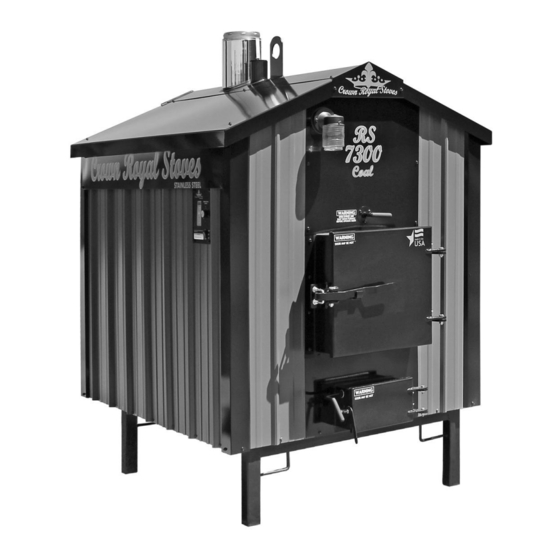
Models: RS7200 • RS7300 • RS7400
UL 391, UL 726 & CSA B366.1
RETAIN THIS MANUAL
CONSERVEZ CE MANUEL
Advertisement
Table of Contents
Troubleshooting

Related Manuals for Crown Royal Stoves RS7200


Summary of Contents for Crown Royal Stoves RS7200
- Page 1 OWNER’ S MANUAL Models: RS7200 • RS7300 • RS7400 Installation, Operation & Maintenance Manual RETAIN THIS MANUAL CONSERVEZ CE MANUEL UL 391, UL 726 & CSA B366.1 Mailing: PO Box 1237 Ph: 866-361-7355 Fax: 218-283-5786 Shipping: 2716 Crescent Dr Web: www.crownroyalstoves.com...
-
Page 3: Table Of Contents
TABLE OF CONTENTS INTRODUCTIONS/SPECIFICATIONS ....................5 BEST BURN PRACTICES ......................... 7 SAFETY INSTRUCTIONS & PRECAUTIONS ..................9 INSTALLATION ............................10 CONCRETE PAD DIMENSIONS ......................11 CHIMNEY REQUIREMENTS .........................12 TRANSFER LINES...........................13 WATER & ELECTRICAL CONNECTIONS ...................14 PIPING INSIDE BUILDINGS ........................14 WIRING INSIDE BUILDINGS ........................14 ELECTRICAL REQUIREMENTS ......................14 EXISTING HOT WATER HEAT ......................15 WIRE DIAGRAM FOR GAS BOILER .....................16... - Page 5 Crown Royal Stove. Crown Royal Stoves are manufactured with quality workmanship and designed to offer you value now and years to come. We are so confident in the quality of our stoves that each Crown Royal Stove comes with a 20 year limited warranty.
- Page 7 Learn how to get the best burn possible from your Crown Royal Stoves. Instructions - Read and follow all operating instructions supplied by Greentech Manufacturing Inc. Fuels - Only burn coal which is the only approved fuel for your Crown Royal Stove. Burning materials not recommended play a major role in visible emissions.
- Page 9 • All installation and operations must follow federal, provincial, state, and local codes for wire plumbing, and installing chimney. • All work must be performed by qualified personnel only. • Read and understand all precautions before operating the furnace. • Furnace not to be used as a standalone unit.
-
Page 10: Concrete Pad Dimensions
All installation and operations must follow federal, provincial, state, and local codes for wire plumbing, and installing chimney. All work must be performed by qualified personnel only. Location When choosing the location of your furnace you should consider prevailing wind direction, distance from home for refueling and storage, and give consideration for any effect of your neighbors. - Page 11 RS7100 RS7200 RS7300 RS7400 RS7500 47.5" 53" 53" 65" 82" 49" 56" 67" 83" 92" 18" 18" 18" 18" 14" 18" 18" 18" 14" 5.5" 9" 9" 12" 14" 9" 9" 12" 14" 28.75" 28.75"...
- Page 12 It is recommended that only a double insulated, stainless steel, Class A chimney pipe to be used. The RS7200 & RS7300 use a six (6) inch diameter pipe, RS7400 uses an eight (8) inch diameter pipe; RS7500 uses a ten (10) inch diameter pipe. Contact your local dealer or Greentech Manufacturing, Inc for chimney purchase information.
- Page 13 Underground insulated pipe is a crucial part of your installation. It is designed to transfer hot water from your furnace to your home, garage or shop. Selecting the correct underground pipe depends on several factors such as climate and distance. Choosing a pipe with the least possible heat loss is the most effective way to ensure your furnaces efficiency.
-
Page 14: Electrical Requirements
Making Water and Electrical Connections at the Stove After the stove has been placed on the concrete or pads, remove the panel at the back of the stove. The return (cold water) pipe must be connected to the fitting at the upper position and the supply (hot water) at the fitting toward the bottom of the stove. - Page 15 ALL INSTALLATIONS AND OPERATIONS MUST FOLLOW FEDERAL, PROVINCIAL, STATE, AND LOCAL CODES FOR WIRING, PLUMBING AND INSTALLING CHIMNEY. ALL WORK MUST BE PERFORMED BY QUALIFIED PERSONAL ONLY. It is recommended that piping used is able to withstand 100 PSI at 180 F, and is at least 1” (inch) in diameter.
- Page 16 Put ‘strap on Aqua stat on the supply side of the water-line from outdoor furnace. Run thermostat wire from the ‘strap on Aqua stat to R and G of fan control center. Run 115V power to white and black wire of fan center coil.
- Page 17 ALL INSTALLATIONS AND OPERATIONS MUST FOLLOW FEDERAL, PROVINCIAL, STATE, AND LOCAL CODES FOR WIRING, PLUMBING AND INSTALLING CHIMNEY. ALL WORK MUST BE PERFORMED BY QUALIFIED PERSONAL ONLY. DOMESTIC HOT WATER The Domestic Hot Water Flat plate Kit consists of a Water to Water Heat Transfer unit and the fittings needed to hook it up.
- Page 19 The Flat Plate Heater can be installed on either the cold side or the hot side of the hot water heater. If installed on the cold side, the hot water heater needs to be left on to maintain the temperature in the hot water heater.
-
Page 20: Water To Air
Water to Air Exchanger Boiler Drain Ball Valve Fitting... -
Page 23: Control Panel
CONTROL PANEL The control panel door is to be shut when fueling the firebox and at all other times except when using the controls. The aqua stat powers the inducer draft blower to maintain the desired water temperature. The aqua stat is set at 160°F at the factory, which means the inducer will run until the water in the jacket reaches 160°F. -
Page 24: Filling Water Jacket
REEREERE FILLING THE WATER JACKET Your outdoor furnace has a vent pipe that protrudes through the roof and is behind the chimney. By placing a garden hose in this pipe you can fill your furnace to the proper water level. Because this furnace is an open-to-atmosphere system, it is normal that water will have to be added annually. -
Page 25: Safety
DAILY FUELING & FIRING ROUTINE Prior to opening the fuel door, pull the damper plate rod out, open the control panel, turn the inducer fan switch off and wait 60 seconds. After the 60 seconds has passed, open the fuel door slowly and stand behind the door so that the door is between you and the fire box. -
Page 26: Starting A Coal Fire
Keep the draft controls open. Once the coal is completely covering the grates and glowing orange you can load more coals and shut the damper controls. Do not fill the unit with more coal than as stated below. RS7200:60 LBS. RS7300:60 LBS. RS7400: 80 LBS. -
Page 27: Annually
Usage of authorized Control chemical is required in all Crown Royal Stoves. To uphold your warranty annual water testing is necessary. Do not allow moisture to come in contact with ashes in firebox. It is mandatory to have a rain cap on the termination of your chimney. -
Page 28: Creosote Formation & Removal
ASH REMOVAL, ROTATION & DISPOSAL CREOSOTE FORMATION & REMOVAL CAUTION! Ashes should never be allowed to When fuel is burned, organic vapors and tar accumulate above the top of the pan. Ashes in combine with expelled moisture forming creosote, contact with the bottom of the grates act as an which clings to the interiors of the stove. - Page 29 If the furnace fails to heat up: • Check fire. • Check fan for operation. • Check that solenoid damper is open to allow air velocity. • Check water level of furnace. • Check for creosote blockage at chimney and bypass trough. •...
- Page 31 Light Solenoid Solenoid Control Panel High Limit Aqua Stat Fan Speed Blower Blower Switch Solenoid Solenoid Load/Line/Neut Blower Blower Grn= Green Blk= Black Wht= White Red= Red Yel= Yellow = Wire nut GREENTECH MANUFACTURING INC. Blk Wht Grn www.green-techmfg.com P:866.361.7355 F:218.283.5786 MATERIAL Power Supply Junction box...
-
Page 33: Smoke Troubleshooting
April 2004 Smoke Troubleshooting Checklist For Outdoor Furnaces Installation Issues (Improper Smoke Dispersal) Chimney height relative to nearest downwind neighbor If located 50 feet or less to any residence not served by the furnace, it is recommended that the stack be at least 2 feet higher than the eave line of that residence. - Page 34 Gasoline Rubber or tires Naphtha Material coated with petroleum products (e.g., particle board, railroad ties, pressure-treated wood) Leaves Paper products or cardboard Operational Issues III. Improper combustion air – Natural Draft Units (No Blower): Air inlet not restricted by debris (creosote, ash, etc.) Flame baffle/flue not restricted by debris Chimney not restricted by debris Door seal in satisfactory condition (provides air-tight seal when...
- Page 35 Discussion Wood, like other fuels is made up of various amounts of carbon, hydrogen, and other elements. The burning of wood is a chemical reaction that depends on many factors. The essential factors to complete wood burning are time, temperature, and turbulence. Some other factors to take into consideration are: intake air;...
- Page 36 Burning materials not recommended by the manufacturer can play a major role in visible emissions. Materials such as plastics, garbage, rubber tires, and even wood products such as cardboard and paper that may be coated with petroleum products may emit excessive smoke.
- Page 37 help reduce smoke is to only burn fuels recommended by the manufacturer and to not overload the furnace. In addition, the furnace size should be properly matched to the heat load so that cold starts and overfilling are avoided. Chimney height should be in accordance with the state and local codes, as well as surroundings, including neighbors.
-
Page 39: Water Treatment
All Crown Royal Stoves are required to be shipped with initial recommended gallon(s) of authorized treatment. Crown Royal Stoves are backed with a 20 Year Limited Warranty. To retain warranty on Crown Royal Stoves it is required to use recommended treatment and submit annual samples for testing. Failure to maintain treatment at recommended levels and annual water testing will result in a voided warranty. - Page 40 Initial Start-up Procedure for Water Treatment All Crown Royal Stoves purchases are required to purchase authorized water treatment for initial start-up. With each gallon of treatment you will be provided with two sample bottles and furnace information forms. • Before adding treatment fill furnace with water and circulate for 48 hrs.
- Page 41 Follow directions for collection of water sample and mail to facility for testing annually. Purchasing Water Treatment Water Treatment is specially formulated for Crown Royal Stoves. To uphold warranty no other chemical may be substituted. We encourage customers to contact your local dealership or call 866-361-7355 to purchase additional water treatment when needed.
- Page 42 EMERGENCY FIRST AID PROCEDURES FOR FURNACE TREATMENT EMERGENCY PHONE NUMBER 1-800-424-9300 INHALATION: Remove from the area to fresh air. If not breathing, clear the airway and start mouth to mouth artificial respiration. GET IMMEDIATE MEDICAL ATTENTION. EYE CONTACT: Immediately rinse the eyes with water. Remove any contact lens and continue flushing for at least 15 minutes.
- Page 43 Thank you for making the choice to purchase your new Crown Royal Stove. We are certain that you will find great satisfaction with your stove’s ongoing reliability and performance. Greentech Manufacturing, Inc. warrants this furnace, to the original owner, to be free of defects in material and workmanship for a period of twenty (20) years from the date of purchase.
-
Page 45: Warranty Claim Form
Warranty Claim Form Date: Distributor/Dealer Name: Address: City: State: Zip: Phone: Fax: Customer’s Name: Address: City: State: Zip: Phone: Fax: Claim conditions apply and cannot exceed warranty statement and procedure policy! Please send this form, bill of sale and pictures back to jessica@green-echmfg.com. arranty work completed without prior authorization may be denied. - Page 46 Have you turned in a warranty claim before? YES or NO If yes, is the leak in the same place? Yes or No Additional Notes or Comments: Repair Required:...
-
Page 47: Precautions
16E09-101 Universal Electronic Temperature Control INSTALLATION AND OPERATION INSTRUCTIONS Save these instructions for future use! DESCRIPTION The 16E09-101 is a single stage electronic temperature con- trol, with a Nema 1 rated enclosure, and can be used for most applications within the temperature control range of -40° to 220°F, (-40°... -
Page 48: Installation
INSTALLATION To prevent electrical shock and/or equipment dam- The control has a user selection for changing the setpoint to age, disconnect electric power to system at main be either the Cut In or the Cut Out setting. The user must be fuse or circuit breaker box prior to installation or careful to understand how this effects the “range”... -
Page 49: Wiring
WIRING Wiring Instruction Notes Fig. 3 Line Voltage Application (Power Stealing) Switch Settings Alarm Output For optional connection Switch SW2 must be set for applications as shown: to customer alarm equipment PTC* (See "Special Note" Temperature in "Operation Section" Sensor for Alarm) Line Voltage (Power Stealing) Line Voltage (Non Power Stealing) -
Page 50: User Menu
USER MENU USER MENU OPERATION SETTINGS: Each press of results in forward movement to the next The control has user Menu settings that will determine how Menu item. If you need to change an item “passed”, you the control operates. The unit is shipped with factory de- must repeatedly press , return to the operating mode, fault settings. -
Page 51: Operation
USER MENU Options Menu Factory Press Item Description Default to select Comments Binary Input On or Off The default setting of Off will have no affect on the operation of the thermostat. When set to On, it allows an external binary input (switch or relay) to start a tem- perature set back. - Page 52 OPERATION Lock Panel (LP) Temperature out of range – If the temperature is more than 5° from the setpoint, continuously for the length of time set in The keypad can be locked to prevent unwanted tampering AL, the alarm relay output will close. The delay should be set with the control settings.
-
Page 53: Specifications
SPECIFICATIONS Operating Ambient Ratings (Control Enclosure): Load Output Relay: Ratings (Maximum): Operating Temperature: -29°F to 140°F (-34° to 60°C) 120VAC 208VAC 240VAC Full Load Amps NC & Load 16 A 9.2 A Storage Shipping Ambient Ratings: Locked Rotor Amps NC & Load 96 A 55.2 A 48 A... -
Page 54: Troubleshooting
TROUBLESHOOTING LCD display, display back-light and green status indica- Temperature differential is wider than set: tor LED turn off in Power Stealing mode: - Temperature change of customer's unit is fast, and the This “off” condition is normal for the control in power stealing Anti Short Cycle delay setting may be overriding the “call”... - Page 56 OWNER’ S MANUAL...
Need help?
Do you have a question about the RS7200 and is the answer not in the manual?
Questions and answers