Table of Contents
Troubleshooting

Related Manuals for Crown Royal Stoves RS7200E


Summary of Contents for Crown Royal Stoves RS7200E
- Page 1 OWNER’S MANUAL EPA QUALIFIED RS7200E INSTALLATION OPERATION & MAINTENANCE MANUAL PH 866-361-7355 MAILING PO BOX 1237 FX 218-283-5786 SHIPPING 2716 CRESCENT DR WEB WWW.CROWNROYALSTOVES.COM INTERNATIONAL FALLS, MN 56649...
-
Page 3: Table Of Contents
TABLE OF CONTENTS INTRODUCTION ................................5 BEST BURN PRACTICES ............................7 ADDITIONAL INSTALLATION AND OPERATIONAL CONSIDERATIONS ..........8 GUIDE TO BURNING WOOD ............................ 9 SAFETY INSTRUCTIONS & PRECAUTIONS ...................... 10 PRE-INSTALLATION ............................... 11 CONCRETE PAD DIMENSIONS ..........................12 CHIMNEY ..................................13 TRANSFER LINE - INSTALLATION ........................ -
Page 5: Introduction
U.S. Environmental Protection Agency Certified to comply with 2015 particulate emission standards. Not approved for sale after May 15, 2020. The Model RS7200E was tested to EPA Method 28WHH for wood fired hydronic heating appliances using crib fuel. The appliance had particulate emissions of 0.13 Lbs/Million BTU. -
Page 7: Best Burn Practices
BEST BURN PRACTICES Learn how to get the best burn possible from your Crown Royal Stove. Instructions – Read and follow all operating instructions supplied by Greentech Manufacturing, Inc. Fuels – Only burn wood which is the only approved fuel in your Crown Royal Stove. Burning materials not recommended play a major role in visible emissions. -
Page 8: Additional Installation And Operational Considerations
ADDITIONAL INSTALLATION AND OPERATIONAL CONSIDERATIONS Installation Person (s) operating a Crown Royal Stove must comply with all applicable laws or other requirements, such as state laws or regulations and local ordinances. Person (s) is/are also responsible for operation in a manner that does not create a public or private nuisance condition. -
Page 9: Guide To Burning Wood
GUIDE TO BURNING WOOD The quality of the firewood you burn can have a big effect on the overall performance and efficiency of your furnace. Several factors that affect the burning characteristic of firewood are moisture, tree species and size. It is important that you understand and follow our guidelines when choosing wood as a fuel source. -
Page 10: Safety Instructions & Precautions
SAFETY INSTRUCTIONS & PRECAUTIONS All installation and operation must follow federal, provincial, state, and local codes for wire plumbing, and installing chimney. All work must be performed by qualified personnel only. Read and understand all precautions before operating the furnace. ... -
Page 11: Pre-Installation
PRE-INSTALLATION ALL INSTALLATIONS AND OPERATIONS MUST FOLLOW FEDERAL, PROVINCIAL, STATE, AND LOCAL CODES FOR WIRING, PLUMBING AND INSTALLING CHIMNEY. ALL WORK MUST BE PERFORMED BY QUALIFIED PERSONNEL ONLY. Location When choosing the location of your furnace you should consider prevailing wind direction, distance from home for refueling and storage, and give consideration for any effect on your neighbors. -
Page 12: Concrete Pad Dimensions
For a pad, the width need not be greater than the outside width of furnace. The length of pad should be as long as the outside length dimension and an added length is desirable as a work area at the loading door. A four-foot extension is most commonly used. WARNING!!! Do not install this unit on a combustible surface. RS7200E STOVE FOOTPRINT... -
Page 13: Chimney
CHIMNEY ALL INSTALLATIONS AND OPERATIONS MUST FOLLOW FEDERAL, PROVINCIAL, STATE, AND LOCAL CODES FOR WIRING, PLUMBING AND INSTALLING CHIMNEY. ALL WORK MUST BE PERFORMED BY QUALIFIED PERSONNEL ONLY. Chimneys The size and height all depends on the unit you have purchased and where the unit will be located. Contact your local dealer or Greentech Manufacturing, Inc. -
Page 14: Transfer Line - Installation
TRANSFER LINE – INSTALLATION TRANSFER LINE - INSTALLATION ALL INSTALLATIONS AND OPERATIONS MUST FOLLOW FEDERAL, PROVINCIAL, STATE, AND LOCAL CODES FOR WIRING, PLUMBING AND INSTALLING CHIMNEY. ALL WORK MUST BE PERFORMED BY QUALIFIED PERSONNEL ONLY. Underground insulated pipe is a crucial part of your installation. It is designed to transfer hot water from your furnace to your home, garage or shop. -
Page 15: Installation
INSTALLATION INSTALLATION ALL INSTALLATIONS AND OPERATIONS MUST FOLLOW FEDERAL, PROVINCIAL, STATE, AND LOCAL CODES FOR WIRING, PLUMBING AND INSTALLING CHIMNEY. ALL WORK MUST BE PERFORMED BY QUALIFIED PERSONNEL ONLY. Making Water and Electrical Connections at the Furnace After the furnace has been placed on the concrete or pads, remove the panel at the back of the stove. ... -
Page 16: Existing Hot Water Heat Installation
EXISTING HOT WATER HEAT – INSTALLATION EXISTING HOT WATER HEAT - INSTALLATION ALL INSTALLATIONS AND OPERATIONS MUST FOLLOW FEDERAL, PROVINCIAL, STATE, AND LOCAL CODES FOR WIRING, PLUMBING AND INSTALLING CHIMNEY. ALL WORK MUST BE PERFORMED BY QUALIFIED PERSONNEL ONLY. It is recommended that piping used is able to withstand 100 PSI at 180 F, and is at least 1” (inch) in diameter. 1 ¼” (inch) piping is recommended for larger systems. -
Page 17: Domestic Hot Water & Forced Air Installation
Domestic hot water DOMESTIC HOT WATER & FORCED AIR - INSTALLATION ALL INSTALLATIONS AND OPERATIONS MUST FOLLOW FEDERAL, PROVINCIAL, STATE, AND LOCAL CODES FOR WIRING, PLUMBING AND INSTALLING CHIMNEY. ALL WORK MUST BE PERFORMED BY QUALIFIED PERSONNEL ONLY. DOMESTIC HOT WATER The domestic hot water flat plate kit consists of a water to water heat transfer unit and the fittings needed to hook it up. -
Page 18: Brazed Plate Setup - Installation
Brazed Plate - Installation BRAZED PLATE SETUP - INSTALLATION Brazed Plate Water to Water Exchanger The brazed plate heat exchanger can be installed on either the cold side or the hot side of the hot water heater. If installed on the cold side, the hot water needs to be left on to maintain the temperature in the hot water heater. If installed on the hot side, the hot water heater needs to be turned off and the hot water heater is now a reservoir. -
Page 19: Water To Air Setup - Installation
Water WATER TO AIR SETUP - INSTALLATION Water to Air Exchanger Water to Air Exchanger Boiler Drain Ball Valve Fitting... -
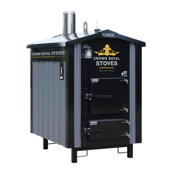
Page 20: Stove Components
Water Level Indicator, Included. Ash Rake for easy cleaning of secondary combustion chamber, Included. Certified Chemical used for water treatment. Specifically designed for use in Crown Royal Stoves to prevent corrosion. REQUIRED ANNUAL WATER TESTING AND USE OF CHEMICAL IS MANDITORY. -
Page 21: Control Panel
Control Panel CONTROL PANEL The aqua stat powers the combustion blower to maintain the desired water temperature. The aqua stat is set at 160°F at the factory, which means that combustion blower will run until the water in the jacket reaches 160°F. As the outside air temperature drops as the season progresses into the winter the settings can be raised to a high of 180°F. -
Page 22: Start Up & Operation
START UP & OPERATION FILLING THE WATER JACKET Your outdoor furnace has a vent pipe that protrudes through the roof and is located in front of the lift hook. By placing a garden hose in this pipe you can fill your furnace to the proper water level. Because this furnace is an open-to – atmosphere system, it is normal that water will have to be added annually. -
Page 23: Operation
OPERATION DAILY FUELING & FIRING ROUTINE Prior to opening fuel door, on the control panel located on the left side of the furnace remember to turn fan/light switch to either off or light position. Next press load switch time delay and wait 20 seconds to allow smoke to evacuate from furnace. -
Page 24: Weekly Maintenance
WEEKLY MAINTENACE WEEKLY MAINTENANCE – Weekly cleaning of heat exchangers and secondary combustion areas are extremely important for the complete process of gasification. Use extreme caution when opening and cleaning doors, these areas will still be hot and could cause personal injury. -
Page 25: General Maintenance
GENERAL MAINTENANCE Usage of authorized Control chemical is required in all Crown Royal Stoves. To uphold your warranty annual water testing is necessary. Do not allow moisture to come in contact with ashes in firebox. Do not rake coals into the secondary burn chamber. It is mandatory to have a rain cap on the termination of your chimney. - Page 26 Off Season Maintenance At the end of the heating season, shut off the pump, clean firebox, heat exchangers, and secondary burn chamber. Check water level indicator and refill until water is full, take water sample to be sent in for testing, if water treatment is needed turn on the circulation pump for at least four hours to mix the treatment thoroughly, check for leaks and then shut the pump off.
- Page 27 heating season to determine if a buildup is occurring. If creosote has accumulated it should be removed to reduce the risk of a chimney fire. RUNAWAY CHIMNEY FIRE To avoid a chimney fire, ensure that daily, weekly, month and annual maintenance techniques are being followed. If a fire is to occur, close all doors including firebox and heat exchanger doors, shut down the power to the unit.
-
Page 28: Troubleshooting
TROUBLESHOOTING If the furnace fails to heat up: 1. Check fire. 2. Check combustion motor for operation. 3. Check that solenoid damper is open to allow air velocity. 4. Check water level of furnace. 5. Check for creosote blockage at chimney and bypass trough. 6. -
Page 29: Electrical Troubleshooting
ELECTRICAL TROUBLESHOOTING... -
Page 30: Electrical Wire Diagram
ELECTRICAL DIAGRAM... -
Page 31: Hpba Smoke Troubleshooting Checklist
April 2004 Smoke Troubleshooting Checklist For Outdoor Furnaces Installation Issues (Improper Smoke Dispersal) Chimney height relative to nearest downwind neighbor 1. If located 50 feet or less to any residence not served by the furnace, it is recommended that the stack be at least 2 feet higher than the eave line of that residence. - Page 32 Gasoline Rubber or tires Naphtha Material coated with petroleum products (e.g., particle board, railroad ties, pressure-treated wood) Leaves Paper products or cardboard III. Operational Issues Improper combustion air – Natural Draft Units (No Blower): 1. Air inlet not restricted by debris (creosote, ash, etc.) 2.
- Page 33 Discussion Wood, like other fuels is made up of various amounts of carbon, hydrogen, and other elements. The burning of wood is a chemical reaction that depends on many factors. The essential factors to complete wood burning are time, temperature, and turbulence. Some other factors to take into consideration are: intake air;...
- Page 34 Burning materials not recommended by the manufacturer can play a major role in visible emissions. Materials such as plastics, garbage, rubber tires, and even wood products such as cardboard and paper that may be coated with petroleum products may emit excessive smoke. Fire starters such as gasoline, oil, and other chemicals can also make an ordinary wood fuel load seem very dirty once burned.
- Page 35 help reduce smoke is to only burn fuels recommended by the manufacturer and to not overload the furnace. In addition, the furnace size should be properly matched to the heat load so that cold starts and overfilling are avoided. Chimney height should be in accordance with the state and local codes, as well as surroundings, including neighbors.
- Page 36 ...
-
Page 37: Authorized Furnace Treatment
AUTHORIZED FURNACE TREATMENT Greentech Manufacturing, Inc. requires the usage of authorized furnace treatment to be used in all Crown Royal Stoves. Treatment is to be added to furnace water upon initial startup and is required to remain at satisfactory levels throughout the life of the stove. -
Page 38: Furnace Treatment Procedure
Before adding treatment fill furnace with water and circulate for 48 hrs. Check for any leaks before adding treatment. Add initial dosages of treatment for the following models – o RS7200E – Add 1 gallon Follow procedure for collecting water sample below. Procedure for Collecting Water Sample ... -
Page 39: Mandatory Water Treatment & Testing
Follow directions for collecting of water sample and mail to facility for testing annually. Purchasing Water Treatment Water treatment is specially formulated for Crown Royal Stoves. To uphold warranty no other chemical may be substituted. We encourage customer to contact your local dealership or call 866-361-7355 to purchase additional water treatment when needed. -
Page 40: Emergency Procedure For Chemical
EMERGENCY PROCEDURE FOR CHEMICAL EMERGENCY FIRST AID PROCEDURES FOR FURNACE TREATMENT EMERGENCY PHONE NUMBER 1-800-424-9300 INHALATION: Remove from the area to fresh air. If not breathing, clear the airway and start mouth to mouth artificial respiration. GET IMMEDIATE MEDICAL ATTENTION. EYE CONTACT: Immediately rinse the eyes with water. -
Page 41: 20 Year Limited Warranty
20 YEAR LIMITED WARRANTY Thank you for making the choice to purchase your new Crown Royal Stove. We are certain that you will find great satisfaction with your stove’s ongoing reliability and performance. Greentech manufacturing, Inc. warrants this furnace, to the original owner, to be free of defects in material and workmanship for a period of twenty (20) years from the date of purchase. - Page 42 The purchaser assumes all responsibility for the care, maintenance and safe operation of the furnace including the monitoring and adding of an approved furnace treatment. All instructions must be followed in the operator’s manual, certified chemical utilized and water samples tested annually and the warranty registration must be on file at Greentech Manufacturing, Inc.
-
Page 43: Warrenty Claim Form
WARRANTY CLAIN FORM WARRANTY CLAIM FORM Date: ______________________ Distributor/Dealer Name: __________________________________________________________________ Address: ________________________________________________________________________________ City: _______________________________________ State: _________________ Zip: __________________ Phone: __________________________________________ Fax: ___________________________________ Customer’s Name: ________________________________________________________________________ Address: ________________________________________________________________________________ City: _______________________________________ State: _________________ Zip: __________________ Phone: ___________________________________________ Fax: __________________________________ Claim conditions apply and cannot exceed warranty statement and procedure policy! Please send this form, bill of sale and pictures back to Jessica@green-techmfg.com. - Page 44 Have you turned in a warranty claim before? Yes or No If yes, is the leak in the same place? Yes or No Additional Notes or Comments: __________________________________________________________________________________________ __________________________________________________________________________________________ __________________________________________________________________________________________ __________________________________________________________________________________________ __________________________________________________________________________________________ __________________________________________________________________________________________ Repair Required: __________________________________________________________________________________________ __________________________________________________________________________________________ __________________________________________________________________________________________ __________________________________________________________________________________________ __________________________________________________________________________________________ __________________________________________________________________________________________...
-
Page 45: Electronic Temperature Control Manual (16E09-101)
16E09-101 Universal Electronic Temperature Control INSTALLATION AND OPERATION INSTRUCTIONS Save these instructions for future use! DESCRIPTION The 16E09-101 is a single stage electronic temperature con- trol, with a Nema 1 rated enclosure, and can be used for most applications within the temperature control range of -40° to 220°F, (-40°... -
Page 46: Installation
INSTALLATION To prevent electrical shock and/or equipment dam- The control has a user selection for changing the setpoint to age, disconnect electric power to system at main be either the Cut In or the Cut Out setting. The user must be fuse or circuit breaker box prior to installation or careful to understand how this effects the “range”... -
Page 47: Wiring
WIRING Wiring Instruction Notes Fig. 3 Line Voltage Application (Power Stealing) Switch Settings Alarm Output For optional connection Switch SW2 must be set for applications as shown: to customer alarm equipment PTC* (See "Special Note" Temperature in "Operation Section" Sensor for Alarm) Line Voltage (Power Stealing) Line Voltage (Non Power Stealing) -
Page 48: User Menu
USER MENU USER MENU OPERATION SETTINGS: Each press of results in forward movement to the next The control has user Menu settings that will determine how Menu item. If you need to change an item “passed”, you the control operates. The unit is shipped with factory de- must repeatedly press , return to the operating mode, fault settings. -
Page 49: Operation
USER MENU Options Menu Factory Press Item Description Default to select Comments Binary Input On or Off The default setting of Off will have no affect on the operation of the thermostat. When set to On, it allows an external binary input (switch or relay) to start a tem- perature set back. - Page 50 OPERATION Lock Panel (LP) Temperature out of range – If the temperature is more than 5° from the setpoint, continuously for the length of time set in The keypad can be locked to prevent unwanted tampering AL, the alarm relay output will close. The delay should be set with the control settings.
-
Page 51: Specifications
SPECIFICATIONS Operating Ambient Ratings (Control Enclosure): Load Output Relay: Ratings (Maximum): Operating Temperature: -29°F to 140°F (-34° to 60°C) 120VAC 208VAC 240VAC Full Load Amps NC & Load 16 A 9.2 A Storage Shipping Ambient Ratings: Locked Rotor Amps NC & Load 96 A 55.2 A 48 A... -
Page 52: Troubleshooting
TROUBLESHOOTING LCD display, display back-light and green status indica- Temperature differential is wider than set: tor LED turn off in Power Stealing mode: - Temperature change of customer's unit is fast, and the This “off” condition is normal for the control in power stealing Anti Short Cycle delay setting may be overriding the “call”... - Page 53 ...
Need help?
Do you have a question about the RS7200E and is the answer not in the manual?
Questions and answers