
Related Manuals for Worldwel longrun 350LA


Summary of Contents for Worldwel longrun 350LA
- Page 1 INVERTER AC/DC TIG WELDER 350LA, 500LA, 600LA OPERATION MANUAL DO NOT INSTALL, OPERATE OR MAINTAIN THIS MACHINE WITHOUT READING THIS MANUAL AND PLEASE ALWAYS THINK BEFORE YOU ACT. www.worldwel.com...
- Page 2 ■ TECHNICAL SPECIFICATIONS - SUFFICIENT CAPACITY of main transformer by self-manufacturing - ELECTRIC SHOCK PROTECTOR reduces No load voltage to 14VDC for user safety when welder is not in use. - Easy to verify welding current during welding by DIGITAL AMMETER. - Optional REMOTE CONTROL BOX is available for adjusting output current without going back to power source.
- Page 3 General Safe Practices ■ Wear approved safety glasses with side shields under your welding helmet or face shield and at all times in the work area. ■ When working above floor level, use a safety belt to protect yourself from a fall should you get a shock.
- Page 4 1. Welding sparks can cause fire or explosion. ■ Remove fire hazards from the welding area. If this is not possible, cover them to prevent the welding sparks from starting a fire. Remember that welding sparks and hot materials from welding can easily go through small cracks and opening to adjacent areas.
- Page 5 ․ Connect the gas hose to the gas input terminal. ․ If you want to connect the water cooling unit, connect the water hose to WATER IN terminal. ※ Input voltage selection ․ Remove the cover of input voltage selection plate. ․...
- Page 6 [ AIR COOLING ] [ WATER COOLING ] Output connection for stick welding ․ Connect the work cable (which is connected to the work clamp) to the TORCH terminal. ․ Connect the electrode cable (which is connected to the electrode holder) to the METAL terminal.
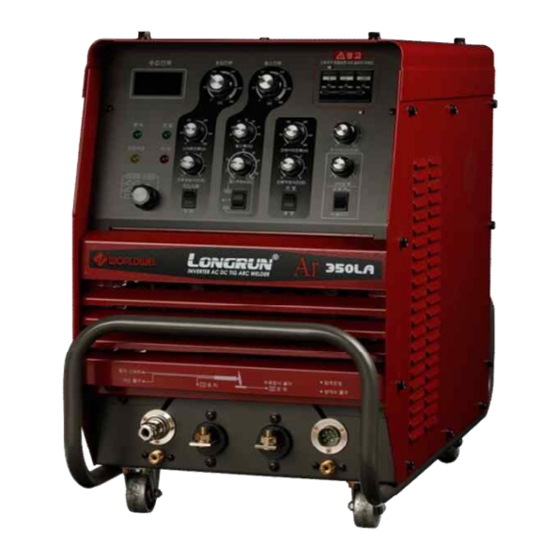
- Page 7 ■ FRONT PANEL When it is turn on, the cooling fan and all of electrical circuit inside the machine Power Switch will be operated. Ammeter Displays the welding current Power Lamp It indicates that the machine is on and input voltage is within acceptable range. It indicates that the machine is ready to run.
- Page 8 It is for checking the flow of the gas. If this switch is ON, then the gas is flowed Gas Check Switch by opening the solenoid valve inside the machine. Pulse Width Control It controls the pulse width It controls the pulse frequency. If the low pulse selected at the pulse frequency Pulse Frequency Control selection switch, apply the inside circle 0.5-25Hz or if the high pulse selected, apply the outside circle 10-500Hz.
- Page 9 ■ Start Up Stick Welding TIG Welding Turn On the main power supplied to welder Turn On the main power supplied to welder Select "WATER COOL" or "AIR COOL" from the Select "STICK" from the welding mode selector Cooling mode selection switch ...
- Page 10 ■ Welding Mode Press and hold the torch switch, the machine will open the gas valve to start the flow of the shielding gas during the pre-flow time and then the arc is started at welding current. When finish to weld, release the torch switch, then the arc is off and flow the gas during the gas Crater Off after-flow time.
-
Page 11: Recommended Action
■ TROUBLESHOOTING SYMPTOMS REASON RECOMMENDED ACTION ․ No input voltage ․ Verify input voltage ․ Fuse (3A) is blown ․ Replace Fuse (3A) Cooling fan does not run when the power switch is turn on. ․ Power switch broke down ․... - Page 14 350LA PARTS LIST PART NAME DESCRIPTION QTY. Control Transformer 9645 Control Transformer 4114 Control Transformer 5719 Main PCB WNLT-01 HF PCB TMD-45A89 Control Transformer PCB VAC-01 PWM PCB WAPD-01 PWM PCB WAPD-02 Relay HR710-2PB DC24V Relay Relay PCB WAPO-01 FUSE MF Condensor 15㎌/800V MF Condensor...
- Page 17 500LA PARTS LIST PART NAME DESCRIPTION QTY. Control Transformer 9645 Control Transformer 4114 Control Transformer 5719 Main PCB WNLT-01 HF PCB TMD-45A89 Control Transformer PCB VAC-01 PWM PCB WAPD-01 PWM PCB WAPD-02 Relay HR710-2PB DC24V Relay Relay PCB WAPO-01 FUSE MF Condensor 20㎌/800V MF Condensor...
- Page 20 600LA PARTS LIST PART NAME DESCRIPTION QTY. Control Transformer 9645 Control Transformer 4114 Control Transformer 5719 Main PCB WNLT-01 HF PCB TMD-45A89 PWM PCB WAPD-01 PWM PCB WAPD-02 Relay HR710-2PB DC24V Relay Relay PCB WAPO-01 FUSE MF Condensor 30㎌/800V MF Condensor 10㎌/800V Condensor 3300UF/400V...
- Page 21 The date number is especially important when identifying the correct replacement parts. Complete this form, please fax it to our selling agency in your country or us for warranty statement. WORLDWEL CO., LTD. 11-101, Songlim-dong, Dong-gu, Incheon-city, Korea TEL : +82-32-876-2114 FAX : +82-32-876-2117...
Need help?
Do you have a question about the longrun 350LA and is the answer not in the manual?
Questions and answers