Mitsubishi Electric MR. SLIM PKA Series Service Manual
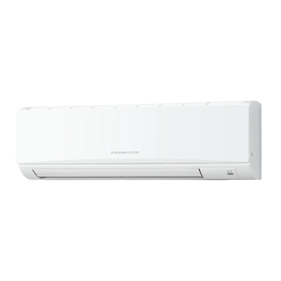
Wall mounted indoor unit
Hide thumbs
Also See for MR. SLIM PKA Series:
- Service manual (42 pages) ,
- Service manual (40 pages) ,
- Service manual (40 pages)
Advertisement
Table of Contents
- 1 Table of Contents
- 2 Reference Manual
- 3 Safety Precaution
- 4 Parts Names and Functions
- 5 Specifications
- 6 Noise Criterion Curves
- 7 Outlines and Dimensions
- 8 Wiring Diagram
- 9 Refrigerant System Diagram
- 10 Troubleshooting
- 11 Function Setting
- 12 Special Function
- 13 Disassembly Procedure
- Download this manual
SERVICE MANUAL
Indoor unit
[Model Name]
[Service Ref.]
PKA-A12HA7
PKA-A12HA7
PKA-A18HA7
PKA-A18HA7
INDOOR UNIT
WIRED REMOTE
CONTROLLER
(Option)
COOL
DRY
AUTO
FAN
HEAT
IR WIRELESS REMOTE
CONTROLLER (Option)
Notes:
CONTENTS
1. REFERENCE MANUAL ................................... 2
2. SAFETY PRECAUTION ................................... 3
3. PARTS NAMES AND FUNCTIONS ................. 5
4. SPECIFICATIONS ........................................... 10
5. NOISE CRITERION CURVES .........................11
6. OUTLINES AND DIMENSIONS ...................... 12
7. WIRING DIAGRAM .........................................13
8. REFRIGERANT SYSTEM DIAGRAM ............ 14
9. TROUBLESHOOTING .................................... 15
10. FUNCTION SETTING ..................................... 29
11. SPECIAL FUNCTION ..................................... 30
12. DISASSEMBLY PROCEDURE ....................... 34
PARTS CATALOG (OCB637)
October 2016
No. OCH637
Advertisement
Table of Contents

Related Manuals for Mitsubishi Electric MR. SLIM PKA Series


Summary of Contents for Mitsubishi Electric MR. SLIM PKA Series
-
Page 1: Table Of Contents
October 2016 No. OCH637 SERVICE MANUAL Indoor unit [Model Name] [Service Ref.] Notes: PKA-A12HA7 PKA-A12HA7 PKA-A18HA7 PKA-A18HA7 CONTENTS 1. REFERENCE MANUAL ........2 2. SAFETY PRECAUTION ........3 3. PARTS NAMES AND FUNCTIONS ....5 4. SPECIFICATIONS ........... 10 5. NOISE CRITERION CURVES ......11 6. -
Page 2: Reference Manual
REFERENCE MANUAL OUTDOOR UNIT SERVICE MANUAL Remote controller (Optional parts) COOL AUTO HEAT OCH637... -
Page 3: Safety Precaution
SAFETY PRECAUTION 2-1. ALWAYS OBSERVE FOR SAFETY Before obtaining access to terminal, all supply circuits must be disconnected. 2-2. CAUTIONS RELATED TO NEW REFRIGERANT Cautions for units utilising refrigerant R410A Use the following tools specifically designed for Use new refrigerant pipes. use with R410A refrigerant. - Page 4 [1] Cautions for service (1) Perform service after recovering the refrigerant left in unit completely. (2) Do not release refrigerant in the air. (3) After completing service, charge the cycle with specified amount of refrigerant. (4) If moisture or foreign matter might have entered the refrigerant piping during service, ensure to remove them. [2] Additional refrigerant charge When charging directly from cylinder Unit...
-
Page 5: Parts Names And Functions
PARTS NAMES AND FUNCTIONS 3-1. Indoor unit Filter Air intake Vane Louver Air outlet 3-2. Wired remote controller (Option) Controller interface The functions of the function buttons change depending on the screen. Refer to the button function guide that appears at the bottom of the LCD for the functions they serve on a given screen. - Page 6 Display The main display can be displayed in 2 different modes: “Full” and “Basic”. The initial setting is “Full”. To switch to the “Basic” mode, change the setting on the Main display setting. (Refer to operation manual included with remote controller.) <Full mode>...
- Page 7 Menu structure Press the button. MENU Main menu Move the cursor to the desired item with the buttons, and press the SELECT button. Vane · Louver · Vent. (Lossnay) High power Timer ON/OFF timer Auto-Off timer Weekly timer OU silent mode Restriction Temp.
- Page 8 Main menu list Setting and display items Setting details Vane · Louver · Vent. (Lossnay) Use to set the vane angle. Use to turn ON/OFF the louver. Use to set the amount of ventilation. High power Use to reach the comfortable room temperature quickly. Timer On/Off timer* Use to set the operation ON/OFF times.
- Page 9 3-3. IR wireless remote controller (Option) CHECK TEST RUN display CHECK and TEST RUN display indicate that the unit is being checked or test-run. MODEL SELECT display Blinks when model is selected. display Lights up while the signal is transmitted to the indoor unit when the button is pressed.
-
Page 10: Specifications
SPECIFICATIONS Service Ref. PKA-A12HA7 Power supply(phase, cycle, voltage) 1 phase, 60 Hz, 208/230 V Max. Fuse Size Min.Circuit Ampacity External finish White Munsell 1.0Y 9.2/0.2 Heat exchanger Plate fin coil Fan(drive) o No. Line flow fan (direct) o 1 0.030 Fan motor output Fan motor 0.33... -
Page 11: Noise Criterion Curves
NOISE CRITERION CURVES PKA-A12HA7 SPL(dB) LINE NOTCH PKA-A18HA7 High NC-70 NC-60 NC-50 NC-40 NC-30 APPROXIMATE THRESHOLD OF HEARING FOR NC-20 CONTINUOUS NOISE 1000 2000 4000 8000 BAND CENTER FREQUENCIES, Hz MAIN UNIT WALL 3.3 ft 3.3 ft MICROPHONE OCH637... -
Page 12: Outlines And Dimensions
OUTLINES AND DIMENSIONS PKA-A12HA7 PKA-A18HA7 Unit: inch (mm) 15-3/16(387) 7-1/2(192) Top side Mount board 23-9/16(599) Front side Right side 9-13/16(249) 3/16(5) Left side 2-1/8 27-1/16(688) 6-1/16(155) (55) Knock out hole 35-3/8(898) Knock out hole for left piping for right piping Front side(Grille open) Sleeve Through hole... -
Page 13: Wiring Diagram
WIRING DIAGRAM PKA-A12HA7 PKA-A18HA7 OCH637... -
Page 14: Refrigerant System Diagram
REFRIGERANT SYSTEM DIAGRAM PKA-A12HA7 PKA-A18HA7 Strainer (#50) Heat exchanger Refrigerant GAS pipe connection (Flare) Pipe temperature Refrigerant flow in cooling termistor/liquid (TH2) Refrigerant flow in heating Condenser/evaporator temperature thermistor (TH5) Refrigerant LIQUID pipe connection (Flare) Room temperature thermistor (TH1) Strainer (#50) Distributor with strainer (#50/#50) OCH637... -
Page 15: Troubleshooting
TROUBLESHOOTING 9-1. TROUBLESHOOTING <Check code displayed by self-diagnosis and actions to be taken for service (summary)> Unit conditions at service Check code Actions to be taken for service (summary) Judge what is wrong and take a corrective action Displayed according to “9-3. SELF-DIAGNOSIS ACTION TABLE”. The trouble is reoccurring. - Page 16 9-2. MALFUNCTION-DIAGNOSIS METHOD BY REMOTE CONTROLLER <In case of trouble during operation> When a malfunction occurs to air conditioner, both indoor unit and outdoor unit will stop and operation lamp blinks to inform unusual stop. < Malfunction-diagnosis method at maintenance service> [Procedure] 1.
- Page 17 Refer to the following tables for details on the check codes. [Output pattern A] Beeper sounds Beep Beep Beep Beep Beep Beep Beep OPERATION · · · Repeated INDICATOR lamp blink pattern Approx. 2.5 s 0.5 s 0.5 s 0.5 s Approx.
- Page 18 On IR wireless remote controller The continuous buzzer sounds from receiving section of indoor unit. Blink of operation lamp On wired remote controller Check code displayed in the LCD. (Refer to the previous page, check code.) If the unit cannot be operated properly after the test run, refer to the following table to find out the cause. Symptom Cause Wired remote controller...
- Page 19 9-3. SELF-DIAGNOSIS ACTION TABLE Check code Abnormal point and detection method Cause Countermeasure 1–3 Room temperature thermistor (TH1) " " " " " 1–3 Pipe temperature thermistor/liquid (TH2) Note: Contact failure of drain float switch (CN4F) Drain over flow protection operation 3–4 1–4.
- Page 20 Check code Abnormal point and detection method Cause Countermeasure Freezing/overheating protection is work- 6–8 1–4 Pipe temperature OCH637...
- Page 21 Check code Abnormal point and detection method Cause Countermeasure 1–3 Condenser/evaporator temperature ther- mistor (TH5) Note: Forced compressor stop (due to water leakage abnormality) Note: Fan motor trouble Remote controller transmission error(E0)/signal receiving error(E4) 1–3, OCH637...
- Page 22 Check code Abnormal point and detection method Cause Countermeasure Remote controller transmission error(E3)/signal receiving error(E5) 4–6 Indoor/outdoor unit communication error (Signal receiving error) 2–4 1–3 Indoor/outdoor unit communication error (Transmitting error) Indoor controller board Remote controller control board Abnormal refrigerant circuit When this error occurs, be sure to replace the 4-way valve.
- Page 23 9-4. TROUBLESHOOTING BY INFERIOR PHENOMENA Note: Refer to the manual of outdoor unit for the detail of remote controller. Phenomena Cause Countermeasure (1)Upward/downward vane The vane is not downward during defrosting and heat Normal operation (The vane is set to performance failure preparation and when the thermostat is OFF in HEAT horizontal regardless of remote control.)
- Page 24 9-5. EMERGENCY OPERATION 9-5-1. When IR wireless remote controller fails or its battery is exhausted When the remote controller cannot be used When the batteries of the remote controller run out or the remote controller malfunctions, the emergency operation can be done using the emergency buttons.
- Page 25 9-6. HOW TO CHECK THE PARTS PKA-A12HA7 PKA-A18HA7 Parts name Check points Room temperature Disconnect the connector then measure the resistance with a tester. thermistor (TH1) (At the ambient temperature 50 to 86_F [10 to 30°C]) Pipe temperature Normal Abnormal thermistor/liquid (TH2) (Refer to “9-6-1.
- Page 26 9-6-2. DC Fan motor (fan motor/indoor controller circuit board) Check method of DC fan motor (fan motor/indoor controller circuit board) Notes · High voltage is applied to the connecter (CNMF) for the fan motor. Pay attention to the service. · Do not pull out the connector (CNMF) for the motor with the power supply on. (It causes trouble of the indoor controller circuit board and fan motor.) Self check...
- Page 27 9-7. TEST POINT DIAGRAM Indoor controller board PKA-A12HA7 PKA-A18HA7 1–3 4–3 5–3 6–3 1–3 CN3C CN22 CN32 CN44 1–2 1–2 3–4 3–4 3–5 OCH637...
- Page 28 9-8. FUNCTIONS OF DIP SWITCH AND JUMPER WIRE Each function is controlled by the DIP switch and the jumper wire on indoor controller board. PKA-A12HA7 PKA-A18HA7 Setting by the DIP switch and jumper wire Jumper wire Functions Remarks MODEL SETTING Model 1 2 3 4 5 settings...
-
Page 29: Function Setting
FUNCTION SETTING 10-1. UNIT FUNCTION SETTING BY THE REMOTE CONTROLLER OCH637... -
Page 30: Special Function
SPECIAL FUNCTION 11-1. Rotation Function (and back-up function, 2nd stage cut-in function) 11-1-1. Operation (1) Rotation function (and Back-up function) Outline of functions System constraint Fig. 1 Refrigerant address Refrigerant address Operation pattern "00" "01" 1 [Back-up function only]··· Request code number "312" Error occurs on main unit. - Page 31 System constraint [2nd stage cut-in function]··· Request code number "322–324" Room temp. ] Set point Room temp. < Set point 7.2°F [ 4:] Start operation Sub unit start operation Sub unit stop Main unit IC-1 unit Stop Stop IC-2 11-1-2. How to set rotation function (Back-up function, 2nd stage cut-in function) (1) Request Code List OCH637...
- Page 32 (2) Rotation and back up operation PAR-3xMAA ("x" represents 0 or later) Main Main menu Maintenance Initial setting Service Main display: Cursor Page Service menu Enter maintenance password 9999 Select: Cursor Service menu Test run Input maintenance info. Function setting Check Self check Main menu:...
- Page 33 11-2. BACK-UP HEATING FUNCTION 11-2-1. Operation The back-up heater turns ON when both of the following conditions have been satisfied: A) When the room temperature has not risen after the heater ON delay time has passed. Note: The heater ON delay time starts when the condition of “set temperature room temperature >...
-
Page 34: Disassembly Procedure
DISASSEMBLY PROCEDURE PKA-A12HA7 PKA-A18HA7 OPERATION PROCEDURE PHOTOS & ILLUSTRATIONS 1. Removing the lower side of the indoor unit from the Figure 1 installation plate Push Corner hole Be careful not to damage the airflow adjustment plate with the Push Down screw driver. - Page 35 OPERATION PROCEDURE PHOTOS 3. Removing the indoor controller board and IR wire- Photo 3 less controller board Photo 4 Photo 5 4. Removing the electrical box Photo 6 OCH637...
- Page 36 OPERATION PROCEDURE PHOTOS 5. Removing the nozzle assembly (with vane and vane Photo 7 motor) and drain hose 6. Removing the indoor fan motor and the line flow fan Photo 8 Photo 9 Photo 10 7. Removing the vane motor Photo 11 OCH637...
- Page 37 OPERATION PROCEDURE PHOTOS 8. Removing the pipe temperature thermistor/liquid Photo 12 and the condenser/evavorator temperature thermis- 9. Removing the heat exchanger Photo 13 10. Removing the room temperature thermistor Photo 14 OCH637...
Need help?
Do you have a question about the MR. SLIM PKA Series and is the answer not in the manual?
Questions and answers